Bias technique for electric utility meter

a technology of bias and electric utility meters, applied in the direction of instruments, measurement using ac-dc conversion, electric devices, etc., can solve the problem that the electric circuit often cannot use the voltage of the ac power lin

Inactive Publication Date: 2007-06-05
ELSTER ELECTRICTY LLC
View PDF261 Cites 28 Cited by
  • Summary
  • Abstract
  • Description
  • Claims
  • Application Information

AI Technical Summary

Benefits of technology

[0010]The inventive method includes receiving an AC voltage from the electric power line, converting the AC voltage to a DC voltage, and adjusting the AC voltage provided to the electronic components, as a function of the AC voltage. The AC voltage provides an electrical reference potential for the electronic components. The inventive method may further comprise increasing the reference-based AC voltage provided to a voltage sensing circuit, while creating a relatively small voltage across the DC power source as a function of the AC voltage. The adjusting may be accomplished by a DC power source, for example, a diode and / or a resistive element in series. The method may further create a DC voltage from the DC power source that biases the AC voltage-based reference potential to a value that permits operation of the electronic components.

Problems solved by technology

Therefore, these electronic circuits often cannot use the AC power line's voltage because it swings below the ground-referenced level or negative power rail.

Method used


Image

  • Bias technique for electric utility meter
  • Bias technique for electric utility meter
  • Bias technique for electric utility meter

Examples


Embodiment Construction

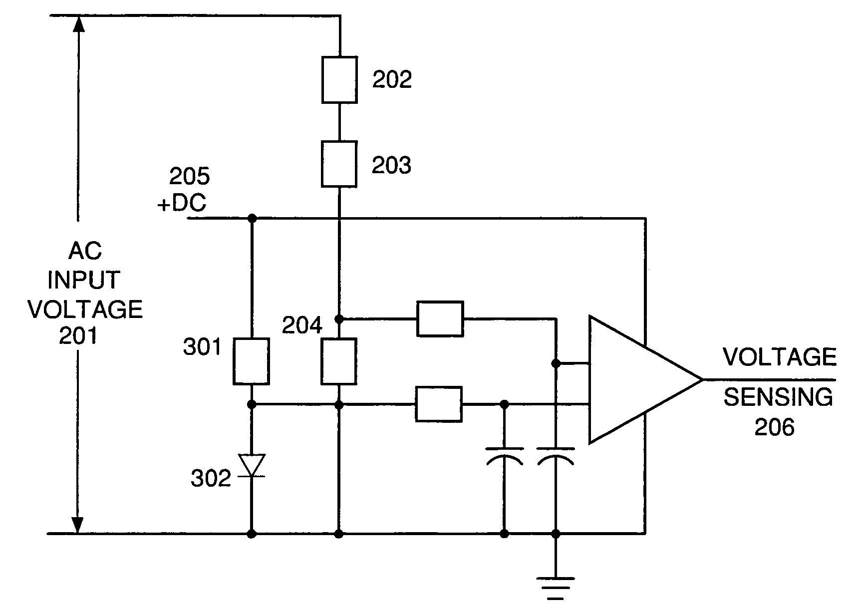
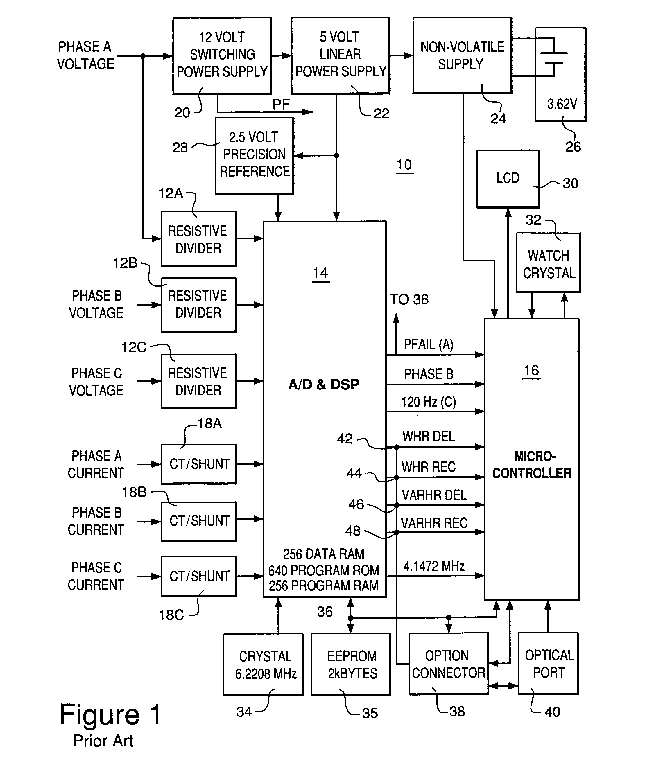
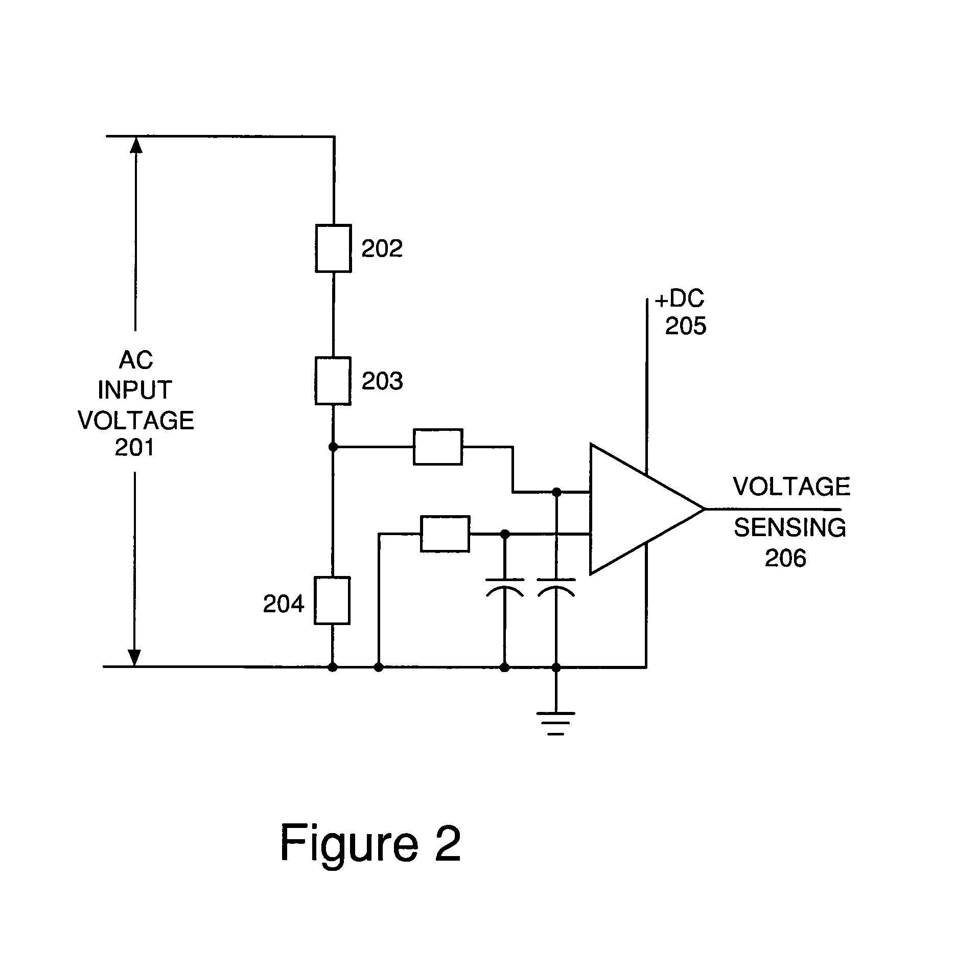
[0016]FIG. 1 is a block diagram of an electronic meter. As shown in FIG. 1, meter 10 is shown to include three resistive voltage divider networks 12A, 12B, 12C; a first processor—an ADC / DSP (analog-to-digital converter / digital signal processor) chip 14; a second processor—a microcontroller 16 which in the preferred embodiment is a Mitsubishi Model 50428 microcontroller; three current sensors 18A, 18B, 18C; a 12 V switching power supply 20 that is capable of receiving inputs in the range of 96-528 V; a 5 V linear power supply 22; a nonvolatile power supply 24 that switches to a battery 26 when 5 V supply 22 is inoperative; a 2.5 V precision voltage reference 28; a liquid crystal display (LCD) 30; a 32.768 kHz oscillator 32; a 6.2208 MHz oscillator 34 that provides timing signals to chip 14 and whose signal is divided by 1.5 to provide a 4.1472 MHz clock signal to microcontroller 16; a 2 kByte EEPROM 35; a serial communications line 36; an option connector 38; and an optical communica...


PUM


Abstract

The invention contemplates an electrical power meter and method of operating the same, where the meter has electronic components (e.g., a power supply and a voltage sensing circuit) and receives alternating current (AC) voltage from an electrical power line. The inventive meter includes a power supply that converting the AC voltage to a direct current (DC) voltage for powering the electronic components. Also, the AC voltage provides an electrical reference potential for the electronic components. The inventive meter further includes a DC power source (e.g., a diode and / or a resistor in series connection) in a parallel circuit configuration with the AC voltage. The DC power source provides a DC bias voltage to the AC voltage. The AC voltage may create a relatively small voltage across the diode device.

Description

FIELD OF THE INVENTION[0001]The invention relates generally to the field of electric utility meters. More specifically, the invention relates to techniques for facilitating efficient operation of electric utility meters.BACKGROUND OF THE INVENTION[0002]Electric utility companies and power consuming industries have in the past employed a variety of approaches to metering electrical energy. Typically, a metering system monitors power lines through isolation and scaling components to derive polyphase input representations of voltage and current. These basic inputs are then selectively treated to determine the particular type of electrical energy being metered. Because electrical uses can vary significantly, electric utility companies have requirements for meters configured to analyze several different nominal primary voltages, the most common of which are 96, 120, 208, 240, 277 and 480 volts root mean squared (RMS).[0003]Electric utility meters employing electronic components instead o...

Claims


Application Information

Patent Timeline
Patent Type & Authority Patents(United States)
IPC IPC(8): G01R11/32G01R15/00G01R21/00G01R21/133H02J1/00H02J13/00H02M7/04
CPCG01R21/133
Inventor SHUEY, KENNETH C.
Owner ELSTER ELECTRICTY LLC
Why Eureka
Try Eureka