Golf alignment device, method and apparatus

a golf alignment and golf technology, applied in the direction of golf accessories, bootlegs, uppers, etc., can solve the problems of many golfers mastering the position of balls with respect, and it is difficult for a golfer to know whether or not he or she is properly aligned with the ball during set-up

Inactive Publication Date: 2007-06-12
ELLIOTT DEANE O
View PDF47 Cites 36 Cited by
  • Summary
  • Abstract
  • Description
  • Claims
  • Application Information

AI Technical Summary

Benefits of technology

[0013]The disclosed invention aids a golfer in achieving and maintaining proper alignment with respect to a target line and / or a reference line. The disclosed invention generates a visible, audible and / or tactile response indicating when a golfer is properly aligned with respect to the intended target line and / or the golf ball.
[0014]One of the more difficult aspects of golf for many golfers is mastering ball position with respect to the golfer's stance. For example, ball position for each of the most commonly-used woods (i.e. the driver, the 3-wood, and the 5-wood) varies according to most schools of thought. As the length of the shaft of the wood increases, the preferred ball position typically moves toward the lead foot of the golfer. However, it is often difficult for a golfer to know whether or not he or she is properly aligned with the ball during set-up. An embodiment of the present invention aids the golfer achieving proper ball position by projecting a light beam toward the tee or the ball at a predetermined angle relative to the golfer's lead foot.

Problems solved by technology

One of the more difficult aspects of golf for many golfers is mastering ball position with respect to the golfer's stance.
However, it is often difficult for a golfer to know whether or not he or she is properly aligned with the ball during set-up.

Method used


Image

  • Golf alignment device, method and apparatus
  • Golf alignment device, method and apparatus
  • Golf alignment device, method and apparatus

Examples


first embodiment

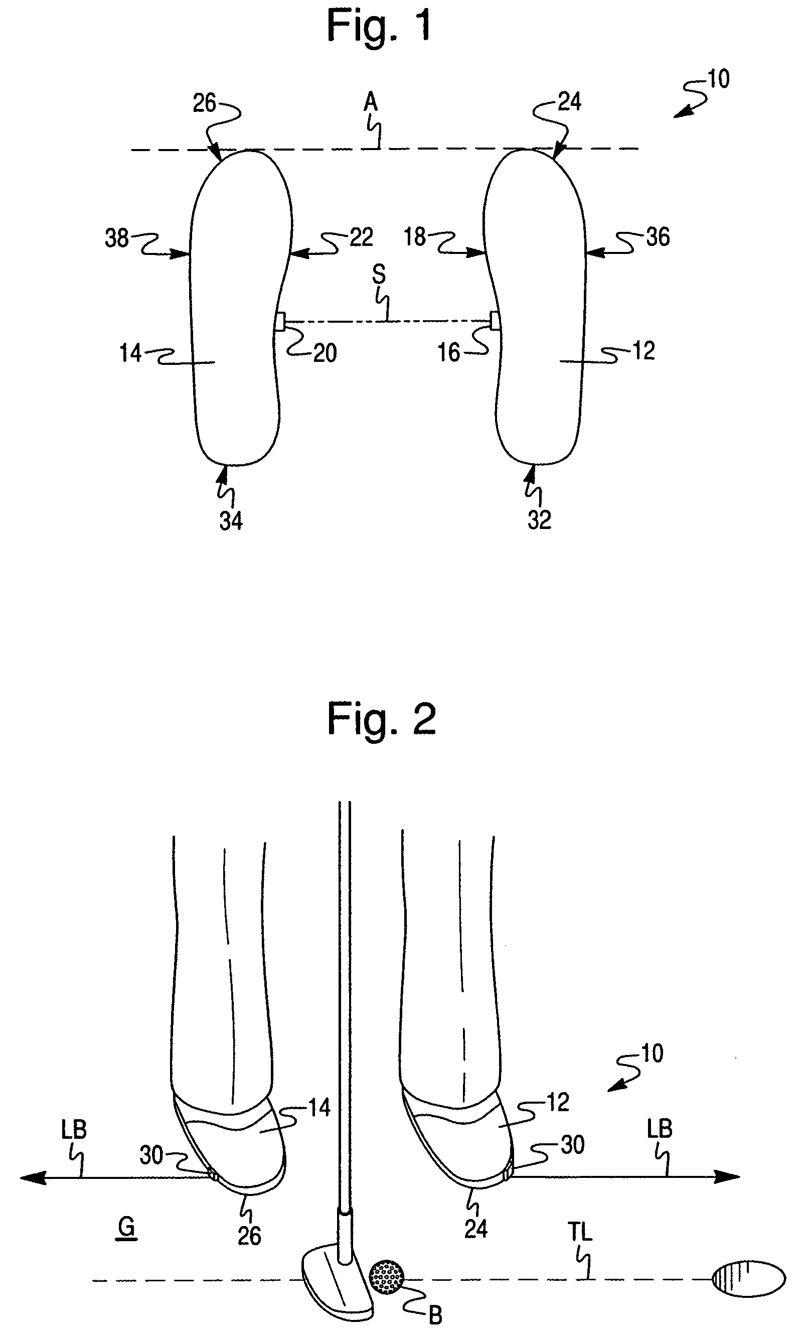
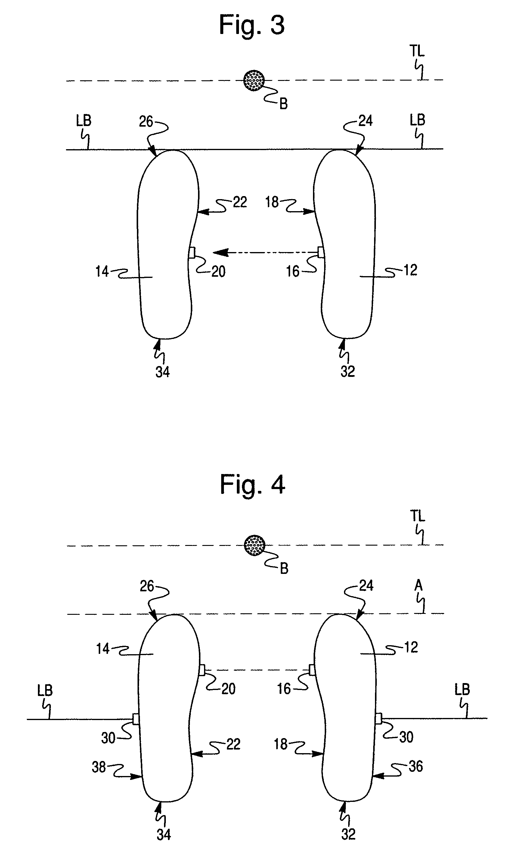
[0047]A golf alignment system 10 according to the present invention is best shown in FIGS. 1 and 2. System 10 includes first and second golf shoes 12, 14 forming a pair. A transmitter 16 is disposed on an instep portion 18 of first golf shoe 12. A receiver 20 is disposed on an instep portion 22 of second golf shoe 14. Transmitter 16 transmits a signal (shown by dashed line S in FIG. 1) which activates receiver 20 when first shoe 12 is in a predetermined position relative to second shoe 14. Transmitter 16 may transmit a radio frequency signal which activates receiver 20. Alternatively, transmitter 16 may transmit a light beam, such as a laser beam; receiver 20 may include a light sensor which is activated by the light beam transmitted by transmitter 16. For example, receiver 20 may be activated by the transmitted signal when first and second shoes 12, 14 are aligned in a ‘square’ set-up position, wherein the toe portions 24, 26 of first and second shoes 12, 14, respectively, are alig...

second embodiment

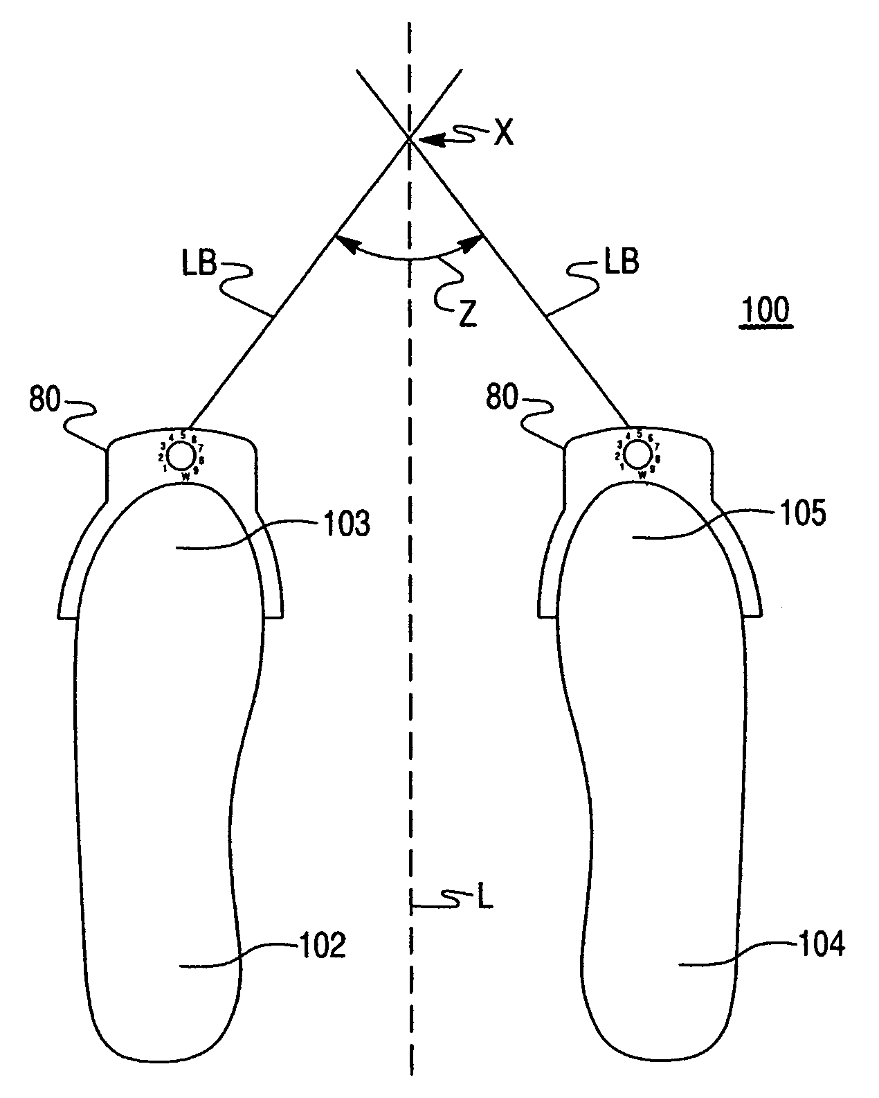
[0052]A golf alignment system 40 is best shown in FIG. 5. System 40 includes first and second golf shoes 42, 44 forming a pair. First shoe 42 includes a light emitting device 46 disposed on an instep portion 48, which projects a light beam LB in a straight line extending outwardly from instep portion 46. Second shoe 44 has a plurality of visual reference marks 50 disposed on an instep portion 52, as best shown in FIG. 6. When the light beam LB is aligned with one of reference marks 50, first shoe 42 is in a predetermined position relative to second shoe 44. First shoe 42 may also include a plurality of light emitting devices 46, wherein each light emitting device 46 emits a light beam that may be aligned with a corresponding reference mark 50, as best shown in FIG. 6A. It should be understood that first shoe 42 may be either a right-footed shoe or a left-footed shoe, depending on the preference of the golfer.

[0053]Alignment of light emitting device(s) 46 with reference mark(s) 50 m...

third embodiment

[0056]A golf alignment system 60 according to the present invention is best shown in FIG. 12. Similar to system 10, system 60 includes first and second golf shoes 62, 64 forming a pair. A transmitter 66 is disposed on an instep portion 68 of first shoe 62. Alternatively, first shoe 62 may also include a two or more transmitters 66 on instep portion 68. Second shoe 64 includes a plurality of receivers 70 disposed on an instep portion 72 thereof. Transmitter(s) 66 transmits a signal which activates a particular receiver 70 depending on the positioning of first shoe 62 relative to second shoe 64. For example, if first and second shoes 62, 64 are in a square position (shown in dashed lines), a central receiver 70a is aligned with and activated by transmitter 66. However, if first shoe 62 is splayed outwardly relative to second shoe 64, another particular receiver 70b is aligned with and activated by transmitter 66 (shown in solid lines).

[0057]Receivers 70 are in communication with a sen...


PUM


Abstract

The present invention is directed to a golf alignment system that generates a visible, audible and / or tactile response indicating when a golfer is properly aligned with respect to an intended target line or to a golf ball. One embodiment includes a first shoe having at least one transmitter disposed on an instep portion thereof. A second shoe has at least one receiver disposed on an instep portion thereof. The receiver is activated by a signal from the transmitter when the first shoe is in a predetermined position relative to the second shoe. Activation of the receiver causes actuation of an indicator, such as a light emitting device which projects a visible reference line on the ground. The present invention is also directed to a method of aligning a golf ball.

Description

CROSS REFERENCE TO RELATED APPLICATION AND CLAIM TO PRIORITY[0001]This application is based on provisional application Ser. No. 60 / 564,218, filed Apr. 22, 2004, by Deane O. Elliot, the disclosure of which is incorporated herein by reference and to which priority is claimed under 35 U.S.C. §119(e)(1).FIELD OF THE INVENTION[0002]The present invention is directed to a golf alignment system that generates a visible, audible and / or tactile response indicating when a golfer is properly aligned with respect to an intended target line or to a golf ball. One embodiment includes a first shoe having at least one transmitter disposed on an instep portion thereof. A second shoe has at least one receiver disposed on an instep portion thereof. The receiver is activated by a signal from the transmitter when the first shoe is in a predetermined position relative to the second shoe. Activation of the receiver causes actuation of an indicator, such as a light emitting device which projects a visible r...

Claims


Application Information

Patent Timeline
Patent Type & Authority Patents(United States)
IPC IPC(8): A43B5/02A63B57/00A63B69/36
CPCA43B1/0036A43B3/0005A43B5/001A63B69/3667A43B3/001A63B69/3608A63B2071/0694A43B3/36A43B3/34
Inventor ELLIOTT, DEANE OWEN
Owner ELLIOTT DEANE O
Why Eureka
Try Eureka