Fixing tool

a tool and fixing technology, applied in the field of fixing tools, can solve the problems of poor workability, difficult handling, poor operability on the lower etc., and achieve the effect of not easily dropping from the chassis and removing from the upper surface side of the chassis

Inactive Publication Date: 2007-06-12
TAKEUCHI KOUGIYOU KK
View PDF13 Cites 40 Cited by
  • Summary
  • Abstract
  • Description
  • Claims
  • Application Information

AI Technical Summary

Benefits of technology

[0006]It is an object of the present invention to provide a fixing tool which can be removed from the upper surface side of the chassis easily and will not drop from the chassis easily.

Problems solved by technology

In this case, since the fitting pieces 32 are small and difficult to hold, they are difficult to handle.
Also, the fitting pieces 32 must be reduced in diameter on the lower surface side of the chassis 2, leading to poor workability.
However, the poor operability on the lower surface side of the chassis 2 cannot be improved.

Method used


Image

  • Fixing tool
  • Fixing tool
  • Fixing tool

Examples


Embodiment Construction

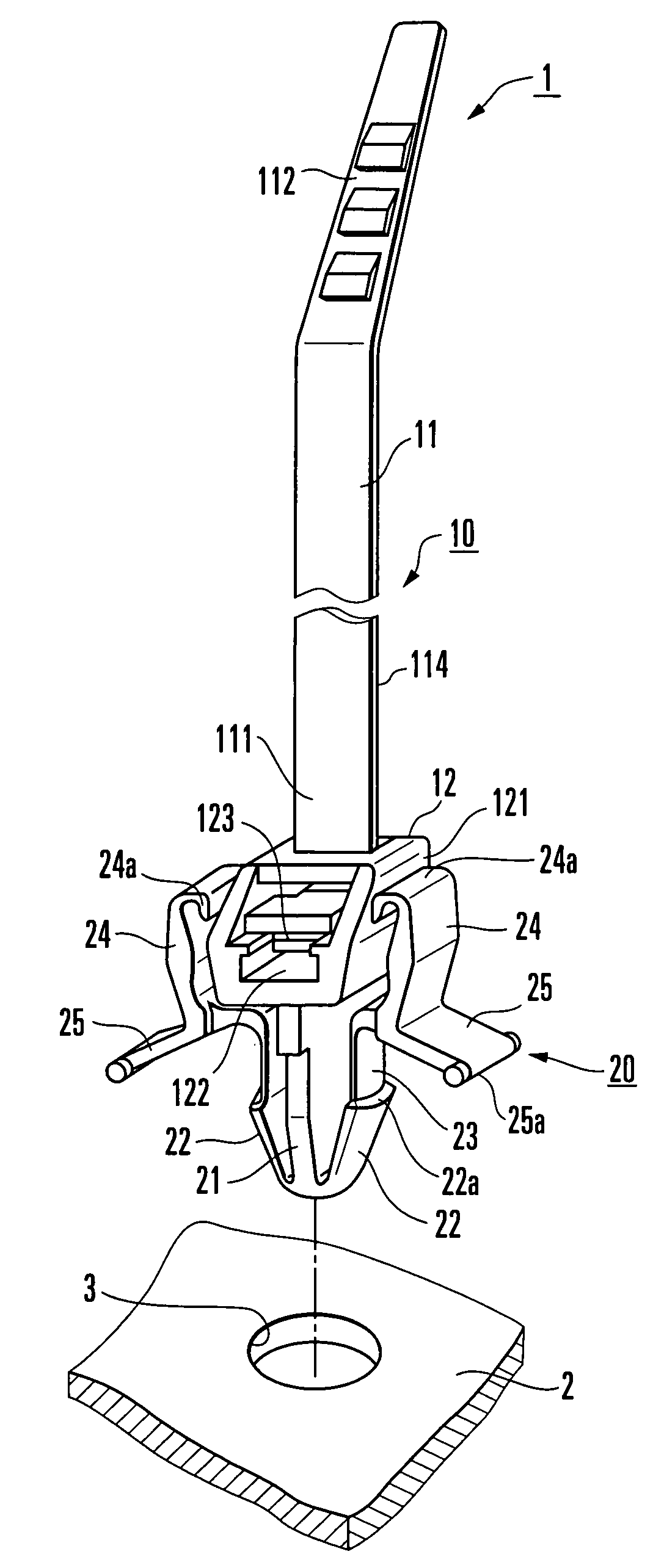
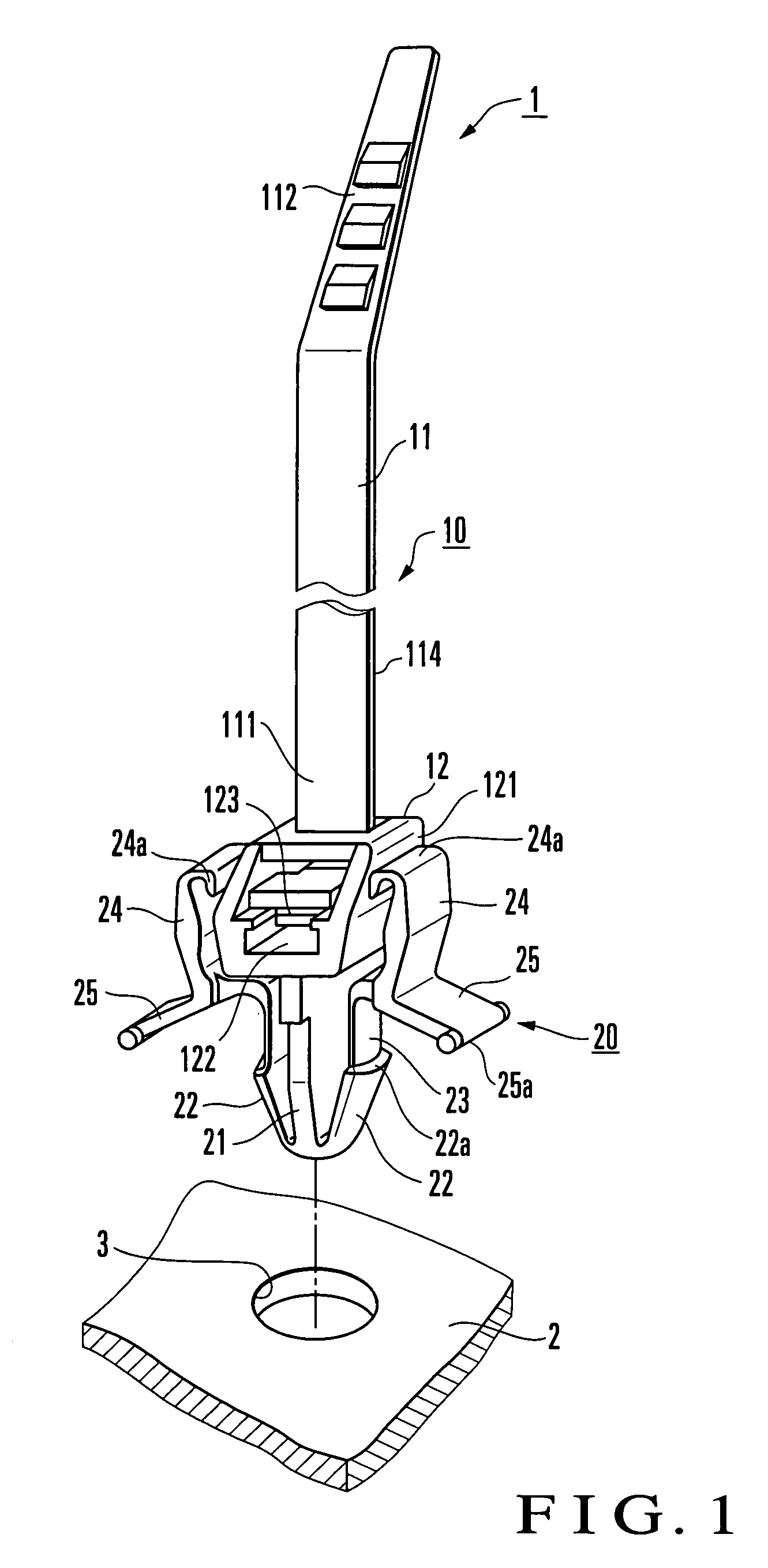
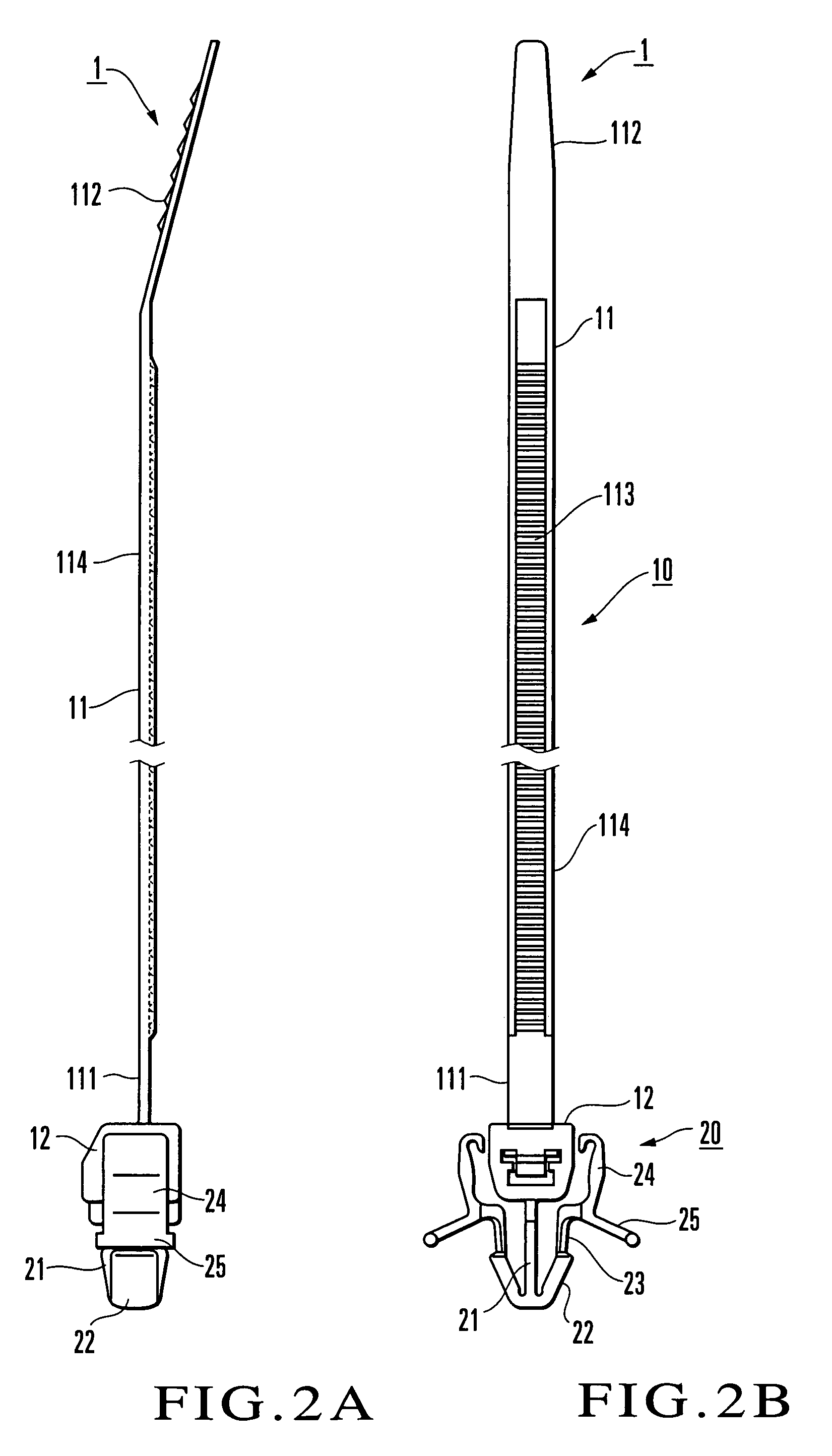
[0020]The embodiments of the present invention will be described with reference to the accompanying drawings. FIG. 1 and FIGS. 2A and 2B show the first embodiment in which a fixing tool of the present invention is applied to a cable tie. FIGS. 3A and 3B show the main part, and FIG. 3C shows a section taken along the line A—A of FIG. 3A. In FIGS. 1 to 3C, a cable tie 1 of the embodiment is formed of a holding portion 10 which ties and fastens cables (not shown), and a fitting portion 20 which is to be fitted in a through hole 3 formed in a chassis 2 so that the holding portion 10 can be attached to the chassis 2. The holding portion 10 and fitting portion 20 are integrally formed by resin molding. The holding portion 10 is formed of a belt portion 11, and a locking portion 12 which locks the belt portion 11 in a state of tying and fastening the cables.

[0021]The structures of the belt portion 11 and locking portion 12 are widely known. The belt portion 11 is formed as a predetermined-...


PUM


Abstract

A fixing tool includes a holding portion and fitting portion. The holding portion allows a chassis to hold a component. The fitting portion is integrally formed with the holding portion and is to be fitted in a through hole formed in the chassis, so that the holding portion is fixed to the chassis. The fitting portion has a post, a pair of fitting pieces, a pair of disengaging pieces, and a pair of leg pieces. The post projects downward from one side of the holding portion. The fitting pieces are formed at a distal end of the post to have an arrowhead-like shape, and elastically deform outwardly in diameter so as to be fitted in the through hole. The disengaging pieces extend from distal ends of the fitting pieces along two side surfaces of the holding portion, and elastically deform the fitting pieces, when operated manually, to disengage them from the through hole. The leg pieces have proximal ends connected to part of the disengaging pieces, and distal ends that can abut against an upper surface of the chassis. The disengaging pieces have extending ends which are close to or connected to the side surfaces of the holding portion.

Description

BACKGROUND OF THE INVENTION[0001]The present invention relates to a fixing tool used to package an electronic component, a cable, or the like on the chassis of an electronic device or the like and, more particularly, to a fixing tool that can be removed from the upper surface of the chassis easily.[0002]When assembling an electronic device, electronic components must be attached to an assembly board such as a panel, chassis, board, or the like (which will be referred to as a chassis hereinafter), and wiring components such as cables must be extended on the board. A mounting component is used for this purpose. For example, when a plurality of cables are to be extended parallel to each other along the surface of a chassis, a cable tie which ties the plurality of cables together and attaches them on the chassis is used. FIG. 12 shows an example of a conventional cable tie. A cable tie 1C has a band portion 11 with one free end that ties a plurality of cables together, and a locking por...

Claims


Application Information

Patent Timeline
Patent Type & Authority Patents(United States)
IPC IPC(8): F16B15/00F16B21/08F16L3/08
CPCF16B21/088F16L3/233Y10T24/1498Y10T24/141
Inventor TAKEUCHI, YASUICHI
Owner TAKEUCHI KOUGIYOU KK
Why Eureka
Try Eureka