Vehicle seat moving devices

a technology for moving devices and vehicle seats, which is applied in the direction of movable seats, roofs, transportation and packaging, etc., can solve the problems of increasing manufacturing costs, difficult to design vehicle seats in a manner, and complicated structure of vehicle seats, so as to reduce the back and forth bending load on the lateral moving element, facilitate the transfer, and facilitate the effect of changing the seat arrangemen

Inactive Publication Date: 2007-06-12
TOYOTA BOSHOKU KK
View PDF3 Cites 33 Cited by
  • Summary
  • Abstract
  • Description
  • Claims
  • Application Information

AI Technical Summary

Benefits of technology

[0006]For example, in one aspect of the present teachings, a vehicle seat moving device may include first and second longitudinal moving mechanisms and a lateral moving mechanism. Each of the longitudinal moving mechanisms has a longitudinal slide rail that is attached to a vehicle floor and a longitudinal slider that is associated with a vehicle seat. The lateral moving mechanism has a lateral moving path that is attached to a vehicle floor and a lateral moving element that is movably attached to the lateral moving path. The lateral moving path is disposed between the first and second longitudinal moving mechanisms so that the lateral moving element can move between the first and second longitudinal moving mechanisms. The longitudinal slider is arranged and constructed to slidably engage to the longitudinal slide rail. Also, the longitudinal slider is arranged and constructed to be engaged with and disengaged from the longitudinal slide rail or the vehicle seat. Further, the lateral moving element can support the vehicle seat thereon when the longitudinal slider is removed from the longitudinal slide rail, thereby permitting lateral movement of the vehicle seat.
[0007]According to this vehicle seat moving device, the vehicle seat can be easily transferred between the first and second longitudinal moving mechanisms. Therefore, it is possible to easily change the seat arrangement, if necessary.
[0008]In addition, the vehicle seat is mounted on the vehicle floor by engaging the longitudinal slider attached to the vehicle seat with the longitudinal slide rail. Therefore, the vehicle seat can be reliably supported on the vehicle floor. As a result, the vehicle seat can sufficiently withstand a large load that can be applied thereto due to a vehicle collision or other such accidents.
[0009]In one embodiment, the lateral moving element can support the vehicle seat thereon in the folded and standing posture when the vehicle seat is moved laterally along the lateral moving path. Therefore, the back and forth bending load imposed on the lateral moving element is effectively reduced. As a result, it is not necessary to use the lateral moving element having higher strength.
[0010]In another embodiment, the lateral moving element comprises a lateral slider that is laterally slidably incorporated in the lateral moving path, According to this construction, the vehicle seat can smoothly move laterally along the lateral moving path.

Problems solved by technology

However, in the vehicle seat moving devices thus constructed, the vehicle seats are supported only by the engagement legs.
Therefore, it is technically difficult to design the vehicle seats in a manner such that the vehicle seats can be reliably supported on the vehicle floor even if a large load is applied thereto due to a vehicle collision or other such accidents.
As a result, the structure of the vehicle seats is complicated.
This may lead to an increased manufacturing cost.

Method used


Image

  • Vehicle seat moving devices
  • Vehicle seat moving devices
  • Vehicle seat moving devices

Examples


Embodiment Construction

[0025]Representative examples of the present invention have been described in detail with reference to the attached drawings. This detailed description is merely intended to teach a person of skill in the art further details for practicing preferred aspects of the present invention and is not intended to limit the scope of the invention. Only the claims define the scope of the claimed invention. Therefore, combinations of features and steps disclosed in the foregoing detail description may not be necessary to practice the invention in the broadest sense, and are instead taught merely to particularly describe detailed representative examples of the invention. Moreover, the various features taught in this specification may be combined in ways that are not specifically enumerated in order to obtain additional useful embodiments of the present invention.

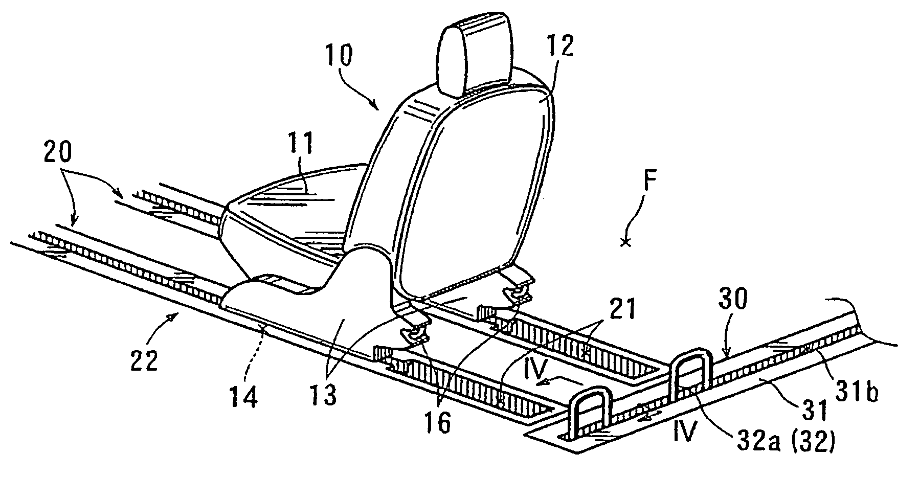
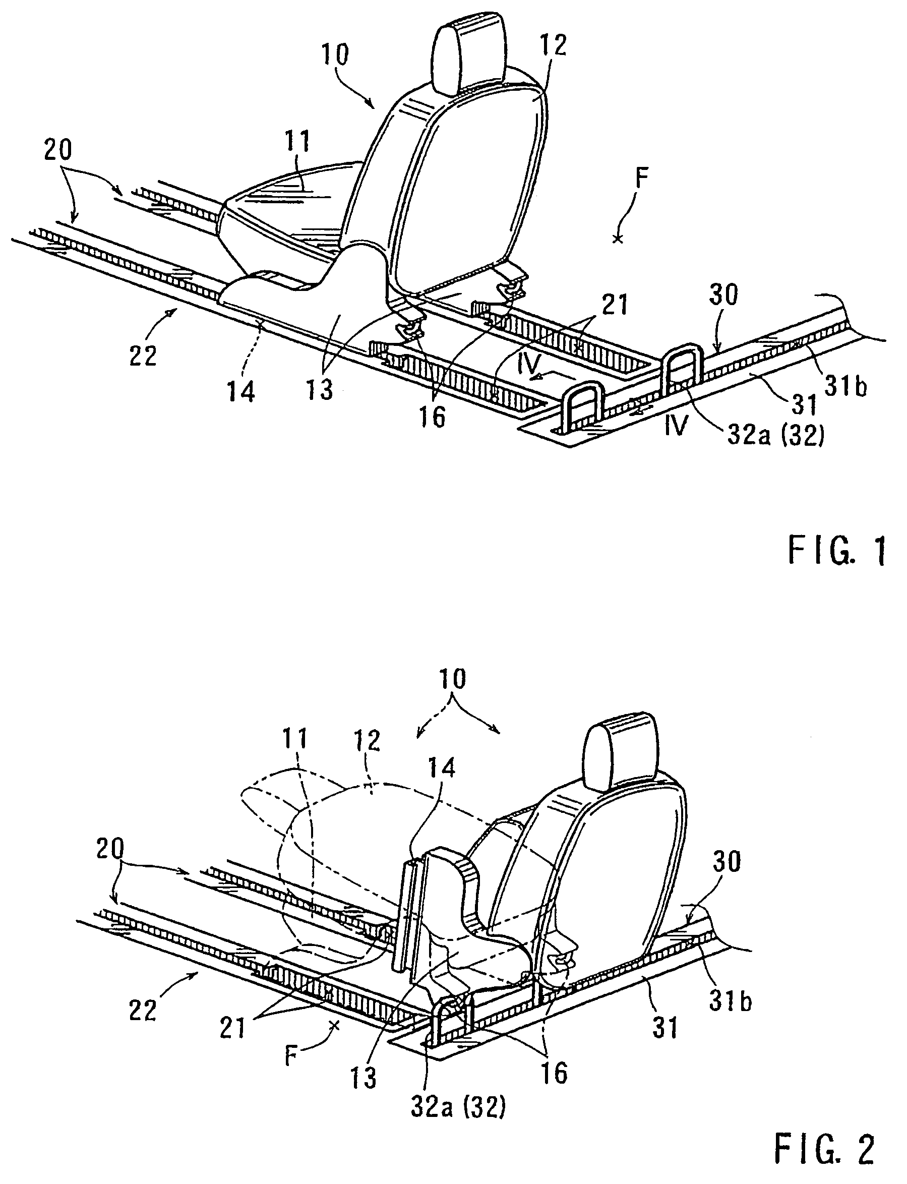
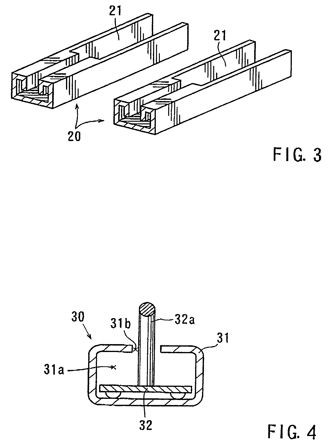
[0026]Five detailed representative embodiments of the present teachings will now be described in further detail with reference to FIG. ...


PUM


Abstract

A vehicle seat moving device may include first and second longitudinal moving mechanisms and a lateral moving mechanism. Each of the longitudinal moving mechanisms has a longitudinal slide rail that is attached to a vehicle floor and a longitudinal slider that is associated with a vehicle seat. The lateral moving mechanism has a lateral moving path that is attached to a vehicle floor and a lateral moving element that is movably attached to the lateral moving path. The lateral moving path is disposed between the first and second longitudinal moving mechanisms so that the lateral moving element can move between the first and second longitudinal moving mechanisms. The longitudinal slider is arranged and constructed to slidably engage to the longitudinal slide rail. Also, the longitudinal slider is arranged and constructed to be engaged with and disengaged from the longitudinal slide rail or the vehicle seat. Further, the lateral moving element can support the vehicle seat thereon when the longitudinal slider is removed from the longitudinal slide rail, thereby permitting lateral movement of the vehicle seat.

Description

BACKGROUND OF THE INVENTION[0001]The present invention relates to vehicle seat moving devices. More particularly, the present invention relates to vehicle seat moving devices that can move a vehicle seat in the longitudinal direction (i.e., the forward and rearward direction) and the lateral direction (i.e., the widthwise direction) of a vehicle in order to rearrange or reposition the vehicle seat.[0002]Various types of vehicle seat moving devices are already known. Such vehicle seat moving devices are taught, for example, by Japanese Laid-Open Patent Publication No. 2002-120604.[0003]In the known vehicle seat moving devices, a vehicle floor is provided with a slide groove that is formed therein in a continuous grid-like pattern. The grid-like slide groove is arranged so as to extend in the longitudinal and lateral directions of a vehicle. Conversely, vehicle seats are respectively provided with engagement legs. The engagement legs of the vehicle seats slidably engage the slide groo...

Claims


Application Information

Patent Timeline
Patent Type & Authority Patents(United States)
IPC IPC(8): B60N2/12
CPCB60N2/0818B60N2/0875B60N2/062B60N2/305B60N2/3093B60N2/3011
Inventor OKUDA, SHINJIAKIYA, HIDEKINIE, TADASHI
Owner TOYOTA BOSHOKU KK
Why Eureka
Try Eureka