

Evaporator for refrigerating cycle
a technology of evaporator and refrigerating cycle, which is applied in the field of evaporators, can solve the problem that condensed water cannot be easily drained out of the evaporator, and achieve the effect of easy and surely drained
- Summary
- Abstract
- Description
- Claims
- Application Information
AI Technical Summary
Benefits of technology
Problems solved by technology
Method used
Image

Examples
first embodiment
[0034]The present invention is explained with reference to embodiments shown in the drawings.
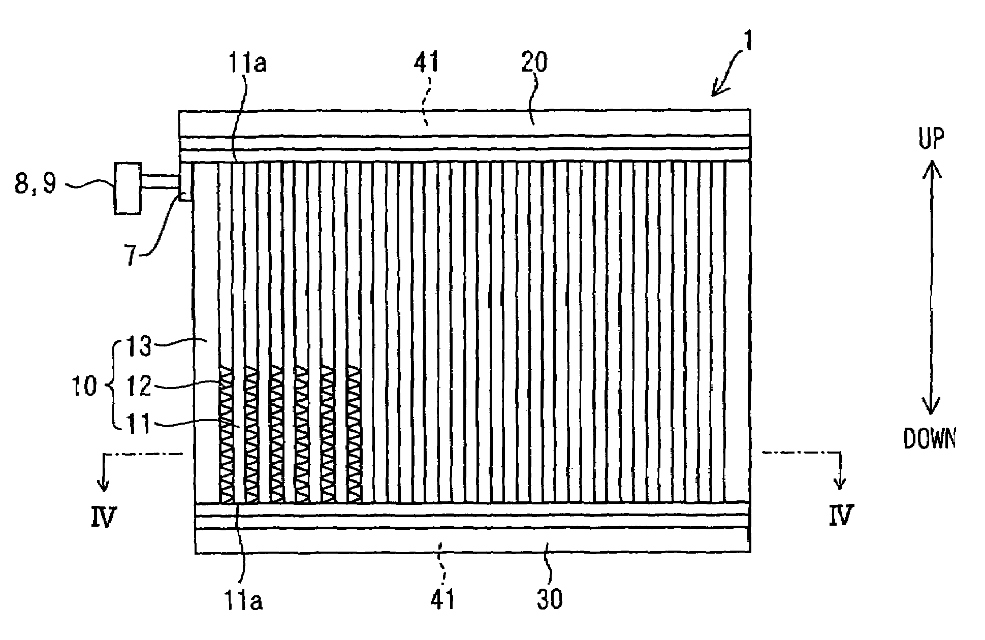
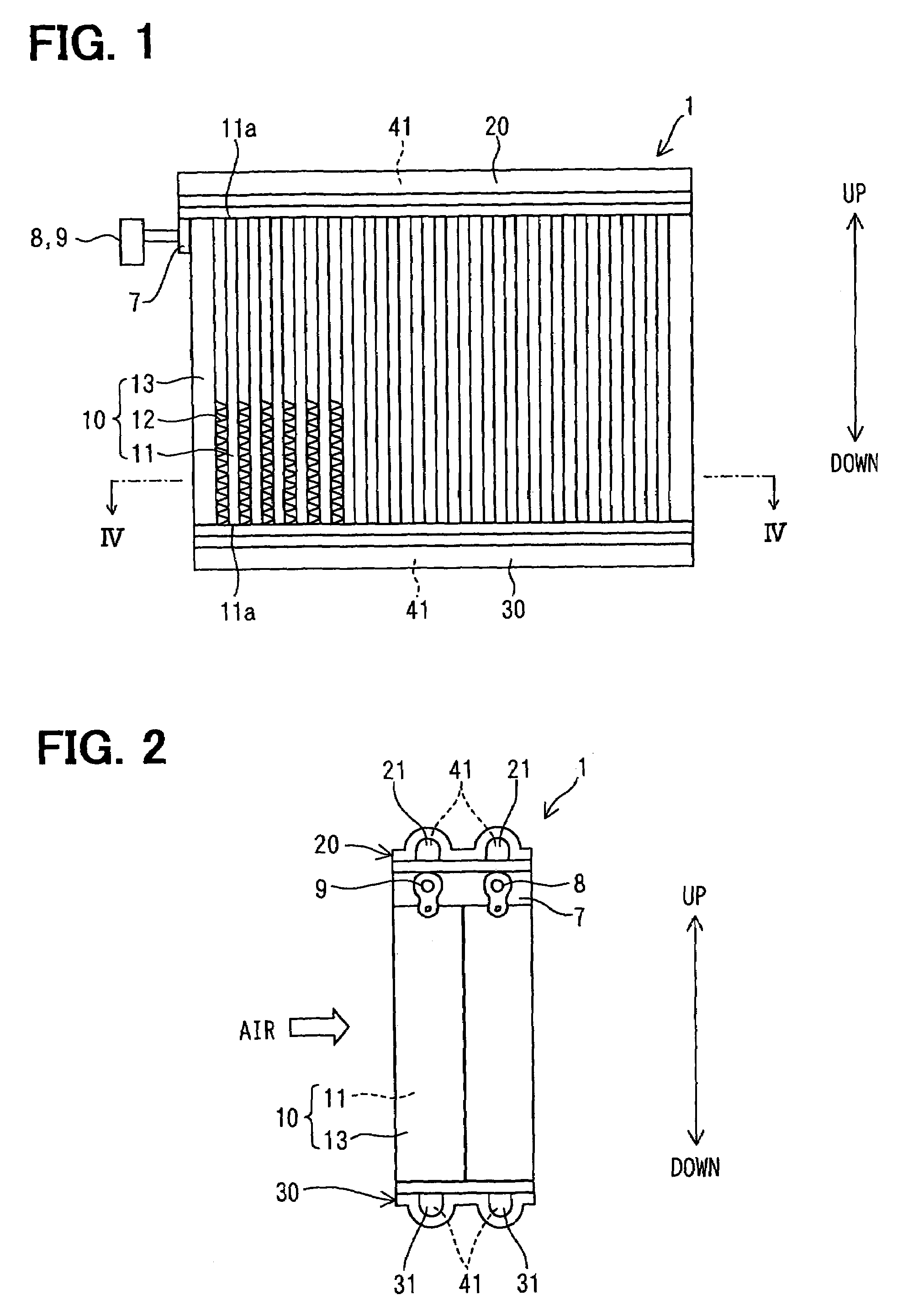
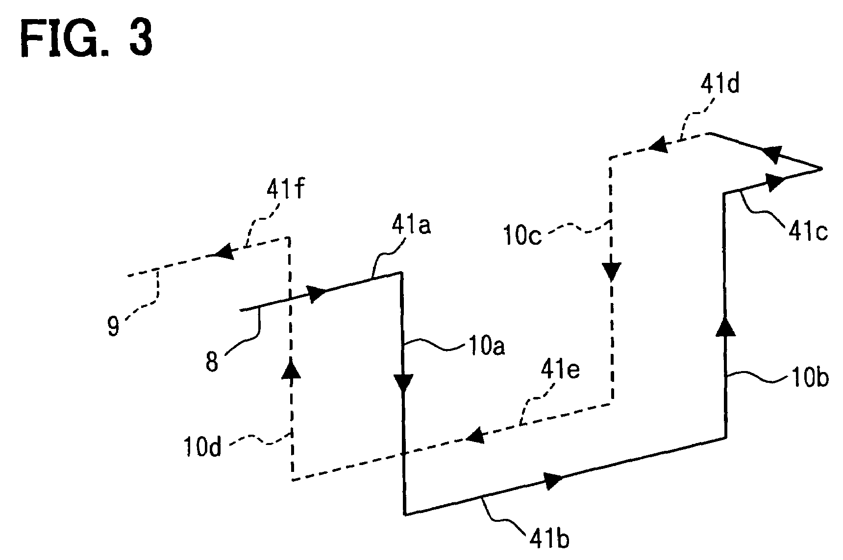
[0035]FIG. 1 is a front elevational view showing an evaporator according to a first embodiment of the present invention, wherein the evaporator is used in a super critical refrigerating cycle operated with refrigerant of carbon dioxide. FIG. 2 is a side view when viewed from a left-hand side. FIG. 3 is a schematic view showing flow of refrigerant in an evaporator. FIG. 4 is a cross sectional enlarged view taken along a line III—III in FIG. 1, wherein tubes are partly shown. FIG. 5 is a cross sectional enlarged view taken along a line V—V in FIG. 4. FIG. 6 is a cross sectional enlarged view taken along a line VI—VI in FIG. 4.
[0036]The super critical refrigerating cycle means a refrigerating cycle in which a pressure of refrigerant on a high-pressure side becomes higher than a critical pressure.
[0037]An evaporator 1 is vertically arranged, as indicated by an arrow, in a unit case (not shown) o...
second embodiment
[0081]A second embodiment is explained with reference to FIGS. 8A and 8B, which correspond respectively to FIGS. 6 and 4.
[0082]As apparent from FIGS. 8A and 8B, the second embodiment differs from the first embodiment in the shape of the drainage means.
[0083]According to the second embodiment, multiple drainage holes 61 are formed in the lower tank 30 in such a manner that the drainage holes 61 vertically pass through the tank element 40 and the tank plate 50 without interfering with the fluid passage portions 41 and the fluid flow spaces 52.
[0084]As in the same manner to the first embodiment, the notched portions 42 are formed in the tank element 40 and the claws 54 formed in the tank plate 50 are downwardly bent to tightly fix the tank element 40 to the tank plate 50.
[0085]With such arrangement of the second embodiment, the condensed water can be surely drained out from the upper surface portions of the lower tank 30 through the drainage holes 61.
third embodiment
[0086]A third embodiment is explained with reference to FIGS. 9A and 9B, which correspond respectively to FIGS. 6 and 4.
[0087]As apparent from FIGS. 9A and 9B, the third embodiment differs from the first embodiment in the notched portion and the claw portions.
[0088]According to the third embodiment, multiple notched portions 55 are formed in the tank plate 50 and multiple claw portions 43 are formed in the tank element 40, wherein the claw portions 43 are upwardly bent to tightly fix the tank element 40 and the tank plate 50 with each other, so that the drainage recesses 60 are likewise formed between the neighboring tubes 11.
[0089]The condensed water flowing down to the upper surface portions of the lower tank 30 flows towards the drainage recesses 60 through spaces 60a between the forward ends 43a of the claw portions 43 and outer side surfaces of the tubes 11. Accordingly, with such arrangement of the third embodiment, the condensed water can be surely drained out from the upper ...
PUM
 Abstract
Description
Claims
Application Information