Fish tank powerhead magnetic holder

a technology of magnetic holder and fish tank, which is applied in the field of magnetic holder, can solve the problems of concomitant movement, contamination of the tank's water, and contamination of the delicately balanced ecosystem

Inactive Publication Date: 2007-06-19
PHIL&DON
View PDF12 Cites 15 Cited by
  • Summary
  • Abstract
  • Description
  • Claims
  • Application Information

AI Technical Summary

Problems solved by technology

Translating movement of the outer assembly causes concomitant movement of the inner assembly, whereby the scrubber surface of the inner assembly is translated across the inner surface of the aquarium wall for cleaning purposes.
This can cause contamination of the tank's water with the oils and dirt associated with human hands.
This contamination can be harmful to the delicately balanced ecosystem within a fish tank, especially within a saltwater fish tank.
However, no means of moving a powerhead other than with hands or another grasping device is disclosed.

Method used


Image

  • Fish tank powerhead magnetic holder
  • Fish tank powerhead magnetic holder
  • Fish tank powerhead magnetic holder

Examples


Embodiment Construction

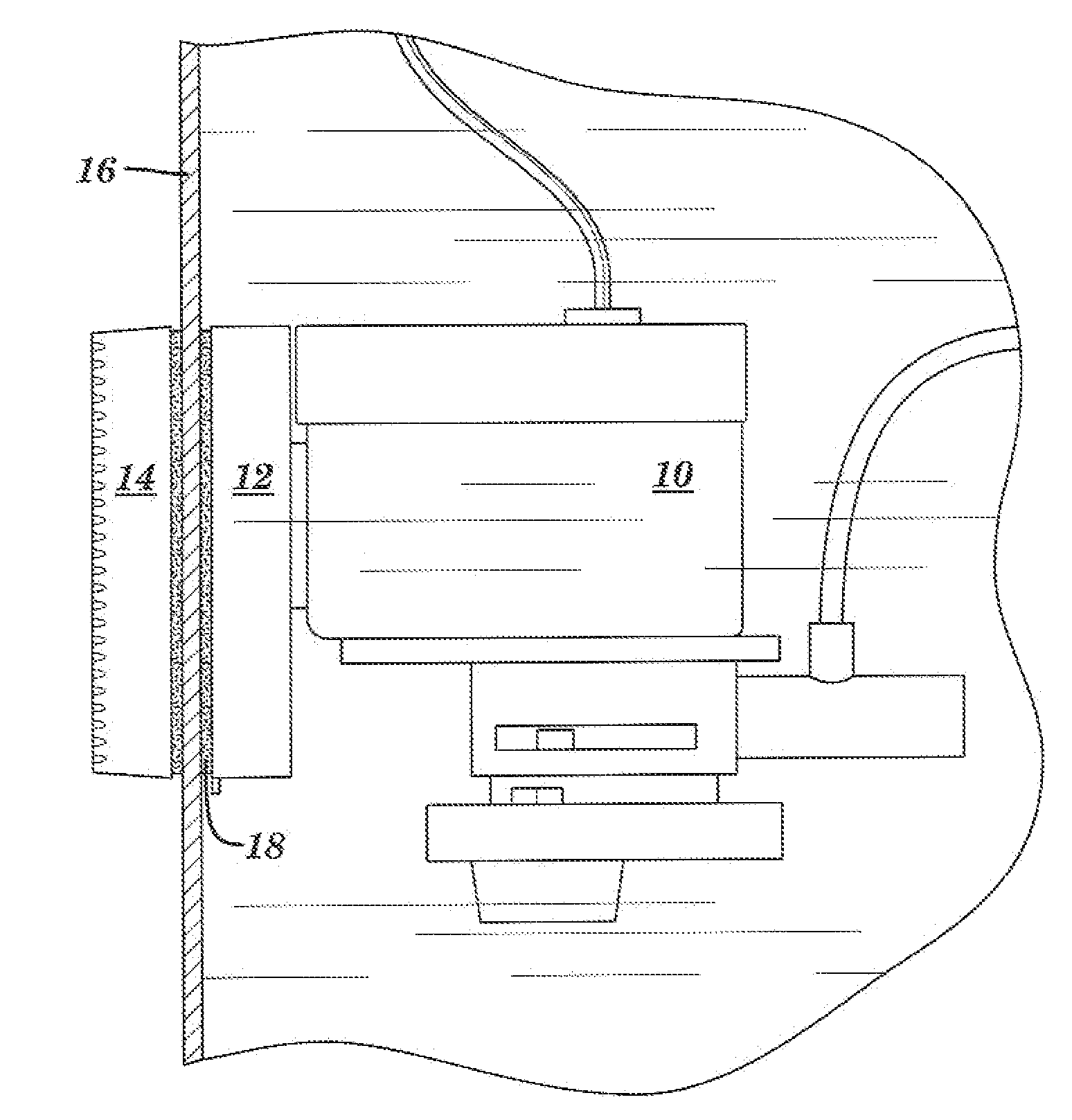
[0022]Referring now to FIG. 1, a commercially available powerhead 10 is shown with a first magnetic assembly 12 permanently affixed 18 thereto, in such a way that the powerhead 10 is able to fully perform its function of aerating a fish tank 16 with the first magnetic assembly 12 attached. The powerhead 10 and first magnet assembly 12 are located inside a fish tank 16, on a vertical wall 16 of the tank 16.

[0023]A second magnetic assembly 14 is also shown. The second magnetic assembly 14 is located on the outside of the fish tank's wall 16, opposite from the first magnetic assembly 12. The second magnetic assembly 14 is a separate unit from the first magnetic assembly 12 and powerhead 10.

[0024]The magnet in the first magnetic assembly 12 is of opposite polarity from the magnet in the second magnetic assembly 14.

[0025]The second magnetic assembly 14 can easily be moved simply by dragging it across the fish tank wall 16. When the second magnetic assembly 16 is thus moved, the first mag...


PUM

PropertyMeasurementUnit
polarityaaaaaaaaaa
magneticaaaaaaaaaa
durableaaaaaaaaaa

Abstract

A fish tank powerhead holding device is taught, the device comprising a first magnetic assembly with a first permanent strong magnet and a non-stick surface adhered to one side, a second magnetic assembly with a second permanent strong magnet that is magnetically attracted to the first magnetic assembly and a non-stick surface adhered to one side, and a commercially available powerhead that is permanently affixed to said first magnetic assembly opposite from said non-stick surface such that the powerhead can be positioned to effectively aerate a fish tank.

Description

CROSS-REFERENCE TO RELATED APPLICATIONS[0001]This non-provisional Application claims the benefit of the filing date of Provisional Application No. 60 / 622,243, filed on 26 Oct. 2004 with the United States Patent and Trademark Office.BACKGROUND OF THE INVENTION[0002]The following section describes the background of the present invention.[0003]1. Field of the Invention[0004]The invention relates to magnetic placement of fresh- and saltwater fish tank aeration devices.[0005]2. Description of Related Art[0006]Musgrave (U.S. Pat. No. 5,778,824) teaches an aquatic animal feeding assembly for use with aquariums, tanks, pools or the like. The feeding assembly comprises an outer magnet placed adjacent to an outer surface of the aquarium wall and an inner magnet placed opposite the outer magnet on the inner surface of the aquarium wall such that the magnets attract each other against the aquarium wall. A food holder is attached to the inner magnet within the aquarium for releasably holding foo...

Claims


Application Information

Patent Timeline
Patent Type & Authority Patents(United States)
IPC IPC(8): A01K63/04C02F1/74
CPCA01K63/042C02F1/74C02F2103/20
Inventor BLUTEAU, PHILIP ANTHONY
Owner PHIL&DON
Why Eureka
Try Eureka