Method and apparatus for detecting electrical faults and isolating power source from the electrical faults

US7233463B2Inactive Publication Date: 2007-06-19PREMIER AVIATION

Image

  • Method and apparatus for detecting electrical faults and isolating power source from the electrical faults
  • Method and apparatus for detecting electrical faults and isolating power source from the electrical faults
  • Method and apparatus for detecting electrical faults and isolating power source from the electrical faults

Examples


Embodiment Construction

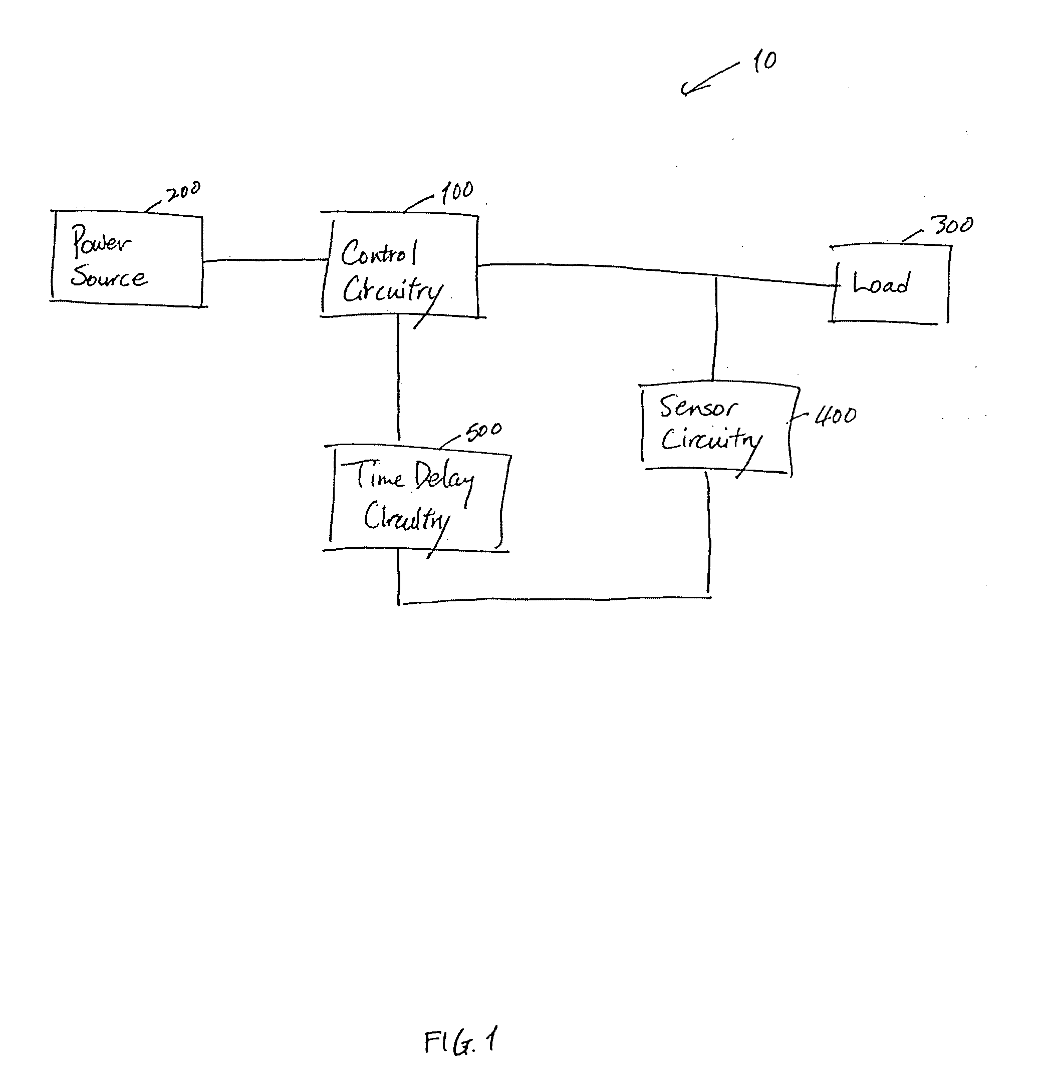
[0023]FIG. 1 illustrates a circuit breaker circuitry in accordance with the present invention that protects against ground faults. It includes a control circuitry 100, a sensor circuitry 400, and a time delay circuitry 500. Control circuitry 100 connects power source 200 to load 300. Sensor circuitry 400 causes control circuitry 100 to isolate power source 200 from circuit breaker circuitry 10 when sensor circuitry 400 detects a electrical fault. When the electrical fault is removed and the control circuitry 100 is reset, control circuitry 100 reconnects power source 200 to circuit breaker circuitry 10. While control circuitry 100 is being reset or when control circuitry 100 initially connects power source 200 to its load, a current spike may occur as a result of connecting load 300 to power source 200. Time delay circuitry 500 isolates sensor circuitry 400 from this current spike to prevent false electrical fault detection. Control circuitry 100, sensor circuitry 400, and time dela...


PUM


Abstract

The present invention is a method and apparatus for protecting a power supply from electrical faults. The present invention operates substantially independently of the current drawn by the load. In addition, the present invention includes a time delay circuitry for preventing false detection of ground faults when the power source is connecting to the load. In a preferred embodiment, the apparatus of the present invention includes a control circuitry for connecting the power supply to the load. The apparatus also preferably includes a sensor circuitry for detecting electrical faults, including ground, transient, and arc faults, and triggering the control circuitry to disconnect the power source from the electrical faults when electrical faults are detected. Thus, the present invention can protect wiring and load connections from improper operation and fire hazards that may be caused by electrical faults. Finally, the apparatus preferably includes a fault protection condition indicator to indicate whether the circuit breaker circuitry is working properly.

Description

CROSS REFERENCE TO RELATED APPLICATION[0001]This application is a continuation of application Ser. No. 10 / 076,177, filed on Feb. 13, 2002, now U.S. Pat. No. 6,650,516, which is a continuation of application Ser. No. 09 / 670,842, filed Sep. 27, 2000, now abandoned, which is a continuation-in-part of application Ser. No. 09 / 603,069, filed on Jun. 26, 2000 now U.S. Pat. No. 6,671,144.FIELD OF THE INVENTION[0002]The present invention relates generally to a circuit breaker circuitry for protecting a power source from electrical faults.BACKGROUND OF THE INVENTION[0003]Many devices known in the art are useful for protecting power sources from electrical faults. There are at least three types of electrical faults: a ground fault, a transient fault, and an arc fault. A ground fault occurs when a grounded conductor comes into contact with electrical circuitry, causing an excessive current flow in that circuitry. A transient fault occurs when a grounded conductor briefly comes into contact with...

Claims


Application Information

Patent Timeline
19 Jun 2007
Publication
US7233463B2
IPC
H02H3/00; H02H1/00; H02H1/04; H02H3/16
CPC
H02H1/0015; H02H3/16; H02H1/04
Inventors
LANGFORD, JOSEPH ANDREW; OSBERNE, GREGORY WARREN