Lubricant supplying device, image forming apparatus and process cartridge

a technology of lubricant supply device and image forming apparatus, which is applied in the direction of engine lubrication, electrographic process apparatus, instruments, etc., can solve the problems of image bearing member wear out due to deterioration, and false detection of the remaining amount of lubrican

Active Publication Date: 2013-09-26
RICOH KK
View PDF6 Cites 18 Cited by
  • Summary
  • Abstract
  • Description
  • Claims
  • Application Information

AI Technical Summary

Benefits of technology

[0014]According to at least one embodiment of the present invention, by detecting the remaining amount during a lubricant supplying operation to a target object of lubrication being stopped, it is possible to detect the length of the solid lubri

Problems solved by technology

If an image forming operation is executed after the lubricant has been completely consumed, the image bearing member wears out due to deterioration because the image bearing member is not protected with the lubricant.
However, in the remaining amount detecting section described in Patent document 1 or 2 which monitors whether the height of the solid lubricant is reduced to less than a prescribed value to detect whether the remaining amount of the solid lubricant becomes only a small amount, there is a problem of a false detection of the remaining amount of the lubricant.
It turns out that the false detection may happen if the detection of the remaining amount is executed while the lubricant is being supplied to a target object of lubrication.
As a result, the contact between the lubricant holding member and the electrode member becomes unsta

Method used


Image

  • Lubricant supplying device, image forming apparatus and process cartridge
  • Lubricant supplying device, image forming apparatus and process cartridge
  • Lubricant supplying device, image forming apparatus and process cartridge

Examples


first modified example

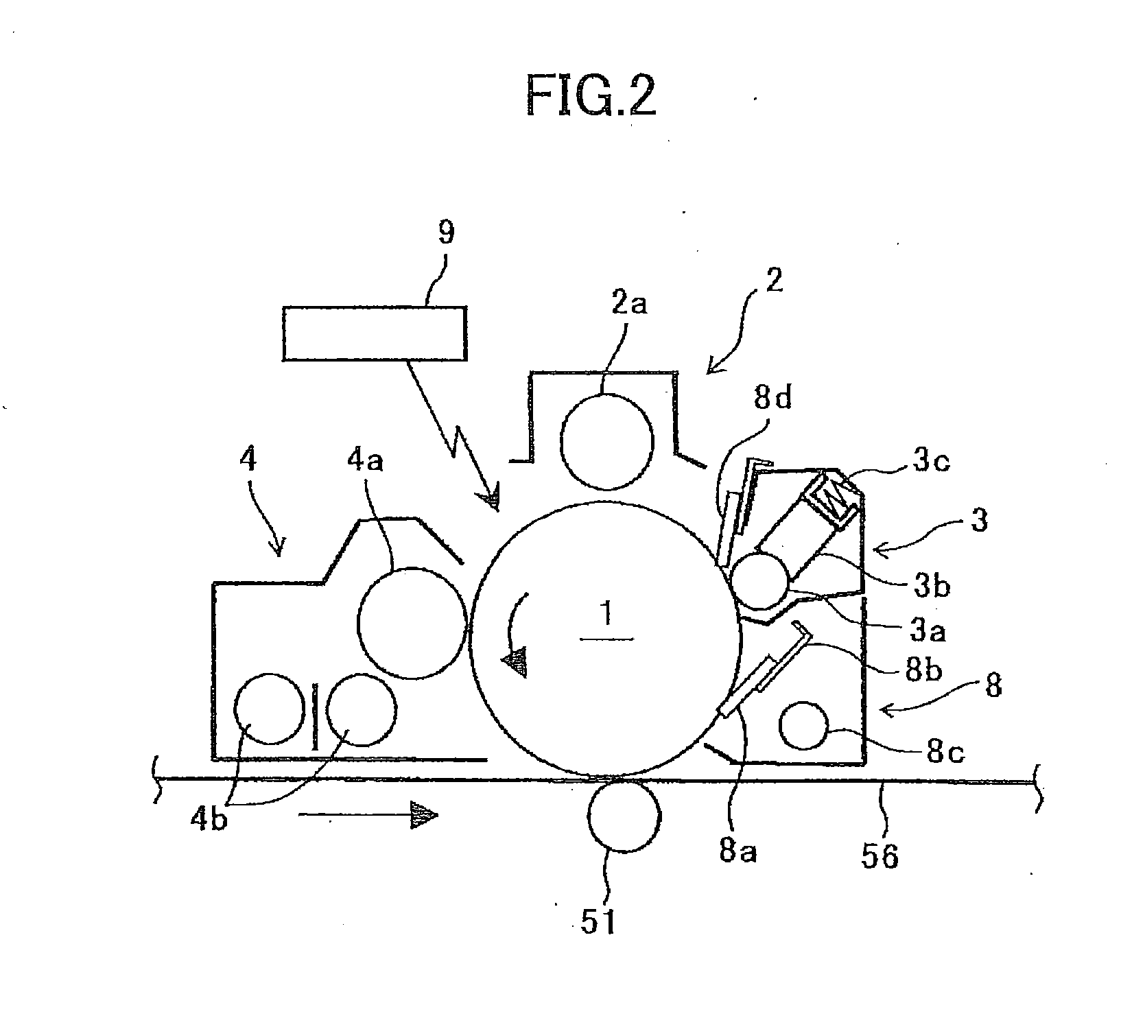
[0100]FIGS. 11A-11B are general configuration diagrams of the first modified example of the remaining amount detecting section 140. FIGS. 12A-12B are cross-sectional views of the first modified example. In FIGS. 12A-12B, a partition wall 143b is not shown. As shown in FIG. 11A, in the first modified example, a rotational electrode 141b, an electrode 142a that comes into contact with the rotational electrode 141b when the solid lubricant 3b becomes the near-end state, a resistance detecting section 142c and the like are included. The resistance detecting section 142c is connected with the electrode 142a and the rotational electrode 141b to apply a voltage between the electrode 142a and the rotational electrode 141b for measuring electronic resistance. The rotational electrode 141b and the electrode 142a are appropriately positioned and supported in a cover member 143. The electrode 142a is disposed over the rotational electrode 141b in the vertical direction.

[0101]An opening 31e is p...

second modified example

[0110]FIGS. 13A-13B are general configuration diagrams of the second modified example of a remaining amount detecting section 240. FIGS. 14A-14B are cross-sectional views of FIGS. 13A-13B taken along the line A-A. FIGS. 15A-15B are cross-sectional views of FIGS. 13A-13B taken along the line B-B. FIG. 13A, FIG. 14A, and FIG. 15A are general configuration diagrams when the solid lubricant 3b is at an early stage of its usage, whereas FIG. 13B, FIG. 14B, and FIG. 15B are general configuration diagrams when the solid lubricant 3b becomes only a small amount (the near-end state). Also, the other end of the lubricant applying device 3 in the longitudinal direction (not shown) is configured in the same way as in the end described here.

[0111]This second modified example of the remaining amount detecting section 240, as shown in FIGS. 13A-13B, has a rotational member 241 and a rotation detecting section 242 to detect rotational movement of the rotational member 241. The rotation detecting se...


PUM


Abstract

A lubricant supplying device used with a solid lubricant, includes a supplying member to supply lubricant taken from the solid lubricant to an object to be supplied with the lubricant, and a remaining amount detecting section to detect a remaining amount of the solid lubricant becoming below a predetermined value. A detection of the remaining amount of the solid lubricant is executed when an operation to supply the lubricant to the object to be supplied with the lubricant stops.

Description

BACKGROUND OF THE INVENTION[0001]1. Field of the Invention[0002]The disclosures herein generally relate to a lubricant supplying device, an image forming apparatus and a process cartridge.[0003]2. Description of the Related Art[0004]It is known that there are image forming apparatuses such as printers, facsimile machines, copying machines, etc., provided with a lubricant supplying device to supply lubricant to a surface of a photoreceptor or an image bearing body, such as an intermediate transfer belt, to protect the image bearing member or to reduce friction.[0005]The lubricant supplying device provides a supplying member making contact with a bar-shaped solid lubricant to be rubbed and scraped off by the supplying member, for generating fine-powder lubricant to be supplied to the image bearing member. The lubricant supplying device also provides a lubricant holding member at the opposing end to the contacting end with the supplying member. The lubricant holding member is held in a...

Claims


Application Information

Patent Timeline
IPC IPC(8): G03G15/00
CPCG03G21/0094G03G15/553
Inventor HONJOH, KENJISHINTANI, TAKESHIYAMAMOTO, KOHSUKETOMITA, DAISUKEKUDO, NORIO
Owner RICOH KK
Why Eureka
Try Eureka