Thermal displacement correction device for machine tool

a technology of thermal displacement correction and machine tool, which is applied in the field of machine tools, can solve the problems of affecting high-accuracy machining, changing mechanical positions, and worsening of correction, so as to reduce false detection and reduce the amount of thermal displacement

Active Publication Date: 2015-10-01
FANUC LTD
View PDF3 Cites 20 Cited by
  • Summary
  • Abstract
  • Description
  • Claims
  • Application Information

AI Technical Summary

Benefits of technology

[0016]The detection result determination unit may be configured to determine the detection result to be based on correct detection if the difference between the actual position and the reference position is within a threshold value. Such an effect is obtained that it can be determined whether or not a detected value is based on correct measurement.
[0017]The threshold value may be obtained by addition of the thermal displacement amount. Such an effect is obtained that the threshold value need not be increased even in machining with large thermal displacement and false detection can be reduced.
[0018]The re-detection unit may be configured to perform detection after shifting a position of detection if it is determined by the detection result determination unit that the detection result is not based on correct detection. Such an effect is obtained that re-detection can be achieved even if chips are caught and prevent correct detection.
[0019]The correction amount modification unit may be configured to obtain an error correction factor from the ratio of the correction error to a thermal displacement amount in the actual position and increase or decrease the thermal displacement amount by multiplying or dividing the thermal displacement amount by the error correction factor. Such an effect is obtained that the correction amount can be modified by a ratio.
[0020]The correction amount modification unit may be configured to add or subtract a value, obtained by subtracting the thermal displacement amount in the actual position from the correction error in the actual position, to or from the thermal displacement amount, to increase or decrease the thermal displacement amount. Such an effect is obtained that the correction amount can be modified by a difference.

Problems solved by technology

The change of the mechanical positions due to heating hinders high-accuracy machining.
According to Japanese Patent Applications Laid-Open Nos. 2002-18677, 2012-101330, and 11-90779, if chips are caught or a coolant splashes so that the result of detection by a position detection sensor is improper, a factor or thermal displacement correction amount may possibly be modified by mistake so that the result of correction becomes worse.
If the calculated drive amount is different from the latter due to deformation of a column or the like, therefore, a problem remains that the thermal displacement cannot be satisfactorily corrected.

Method used


Image

  • Thermal displacement correction device for machine tool
  • Thermal displacement correction device for machine tool
  • Thermal displacement correction device for machine tool

Examples


Embodiment Construction

[0031]A method of detecting the position of a feed shaft will be described first.

[0032]1.

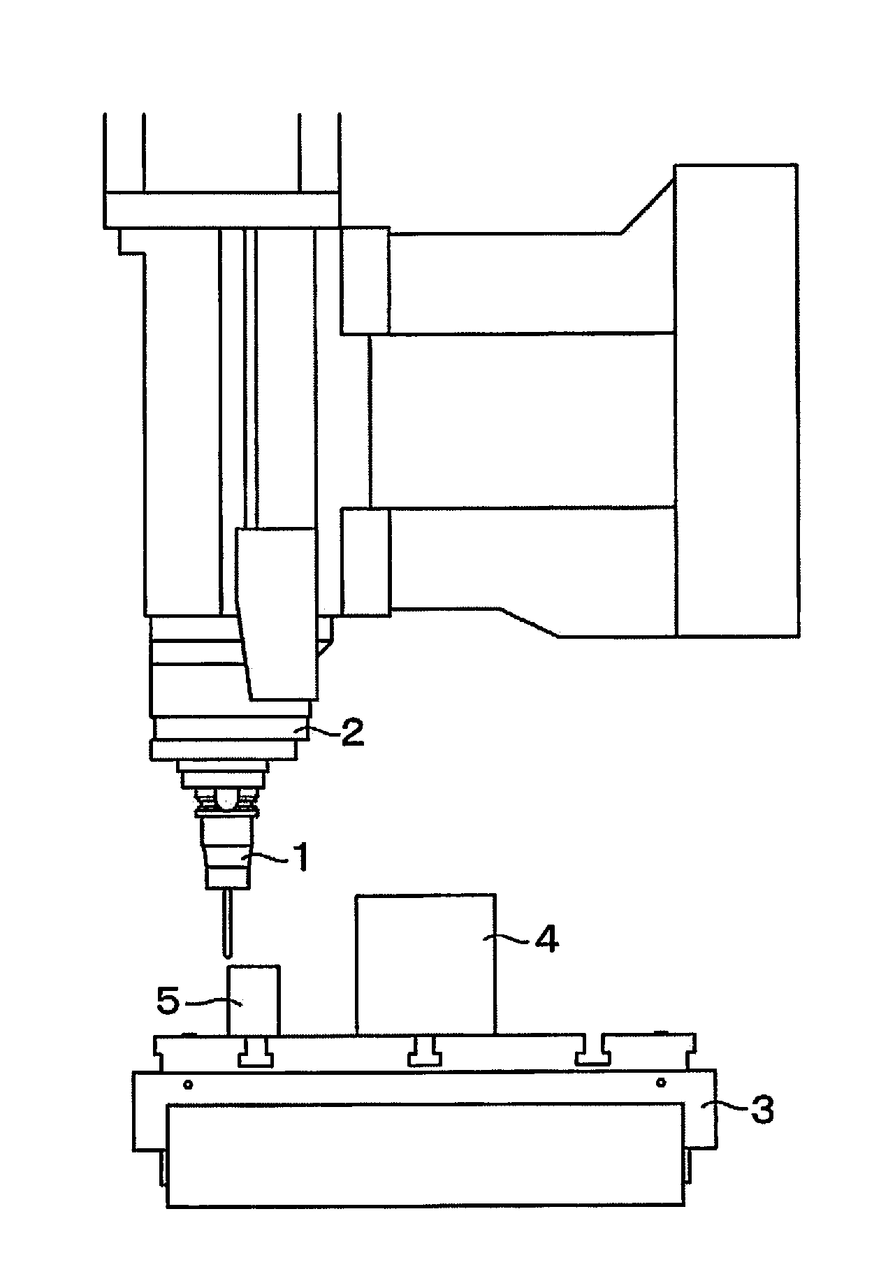
[0033]FIG. 1 is a schematic view showing an example of the installation position of a position detection sensor 1. As shown in FIG. 1, the position detection sensor 1 is held on a spindle 2 and generates a contact signal when it is brought into contact with a jig 5 or a workpiece 4 fixed on a table 3. For example, a touch probe (or touch-type probe) is used as the position detection sensor 1. Since the touch probe also moves as the feed shaft of a machine tool moves, it can make detection from an optimal position and in an optimal direction.

[0034]The position detection sensor 1 is not limited to the touch probe described above, and may alternatively be a contact-type position detection switch such as a limit switch, microswitch, etc., or a non-contact position detection switch such as a magnetic detection switch, inductive proximity switch, capacitive proximity switch, etc.

[0035]For the install...


PUM

PropertyMeasurementUnit
thermal displacementaaaaaaaaaa
timeaaaaaaaaaa
thresholdaaaaaaaaaa

Abstract

A thermal displacement correction device for a machine tool is provided with detection result determination unit configured to determine, based on an actual position and a reference position detected by position detection unit, whether or not the actual position is based on correct detection, correction error calculation unit configured to calculate a correction error in the actual position if it is determined that the result of detection is based on correct detection, and correction amount modification unit configured to modify a thermal displacement correction amount based on the correction error.

Description

BACKGROUND OF THE INVENTION[0001]1. Field of the Invention[0002]The present invention relates to a machine tool, and more particularly, to a thermal displacement correction device for the machine tool.[0003]2. Description of the Related Art[0004]Since a feed screw and a spindle of a machine tool are driven by a motor, they are expanded so that their mechanical positions change due to heating of the motor, frictional heat generated by the rotation of a bearing, and frictional heat from a contact portion between a ball screw and a ball nut of the feed screw. Thus, the relative positions of a workpiece to be positioned and a tool are shifted. The change of the mechanical positions due to heating hinders high-accuracy machining.[0005]The displacement of the mechanical positions due to heating can be eliminated by using a technique in which a command position is corrected based on a displacement or temperature detected by a displacement or temperature sensor or a structure configured to ...

Claims


Application Information

Patent Timeline
Patent Type & Authority Applications(United States)
IPC IPC(8): G01N25/16G01M99/00
CPCG01M99/002G01N25/16B23Q15/18G05B19/404G05B2219/49207
Inventor KOYAMA, YASUAKIMAEKAWA, SUSUMU
Owner FANUC LTD
Why Eureka
Try Eureka