Vehicular input device and vehicular input method

a technology of vehicle input and input method, which is applied in the direction of dashboard fitting arrangement, instruments, transportation and packaging, etc., can solve the problems of erroneously detecting the normal movement of the driver by the proximity sensor, hiding the operation guis of necessary information, etc., and achieve the effect of reducing false detections

Active Publication Date: 2013-04-11
PANASONIC INTELLECTUAL PROPERTY MANAGEMENT CO LTD
View PDF13 Cites 21 Cited by
  • Summary
  • Abstract
  • Description
  • Claims
  • Application Information

AI Technical Summary

Benefits of technology

[0011]The vehicular input device according to the present invention is capable of decreasing false detections caused by an operation such as a driving operation which is an operation other than a contactless input operation.

Problems solved by technology

However, when users including drivers do not perform operations on the operation screens, the operation GUIs showing necessary information are hidden.
However, when the detection sensitivity of the proximity sensor is increased or the sensor is disposed between the driver's seat and the display for the purpose of quickly detecting the movement of the driver for operation that is performed in the proximity of the display, the proximity sensor may erroneously detect a normal movement of the driver for driving a vehicle (hereinafter referred to as “driving operation”).
There is a problem that such a false detection by the proximity sensor causes an operation feedback (for example, a menu is displayed) which is not intended by the driver.

Method used


Image

  • Vehicular input device and vehicular input method
  • Vehicular input device and vehicular input method
  • Vehicular input device and vehicular input method

Examples


embodiment 1

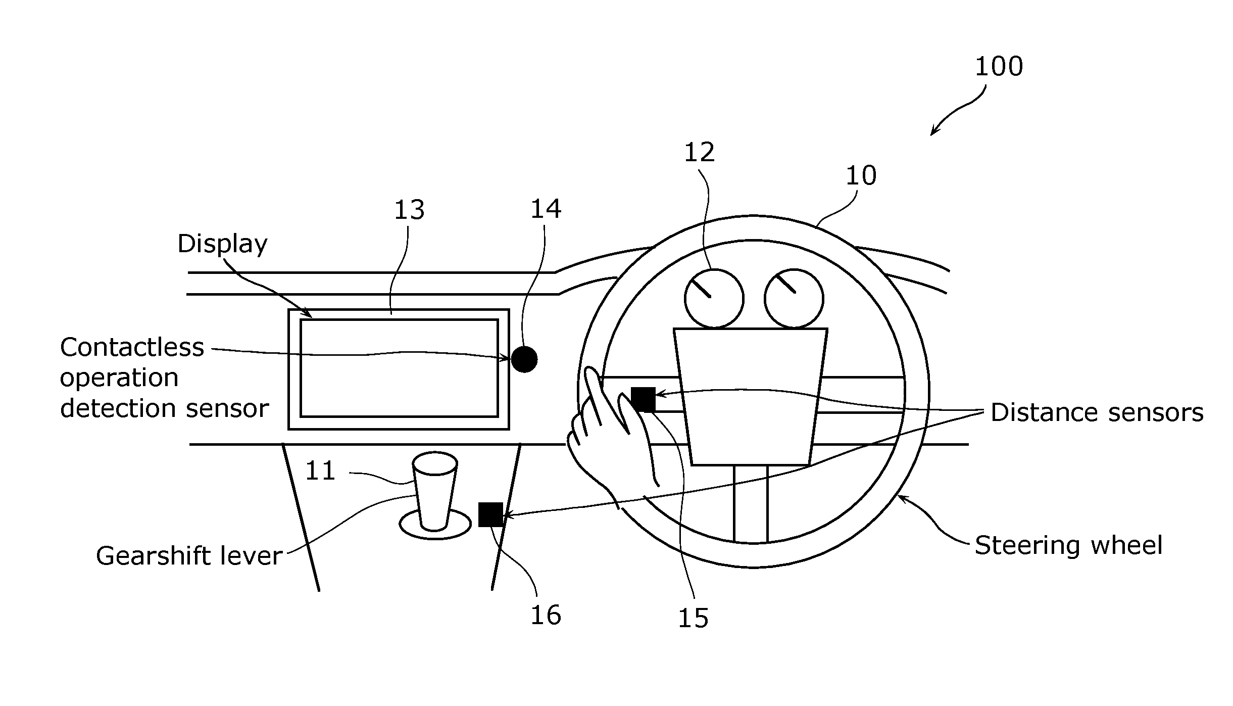
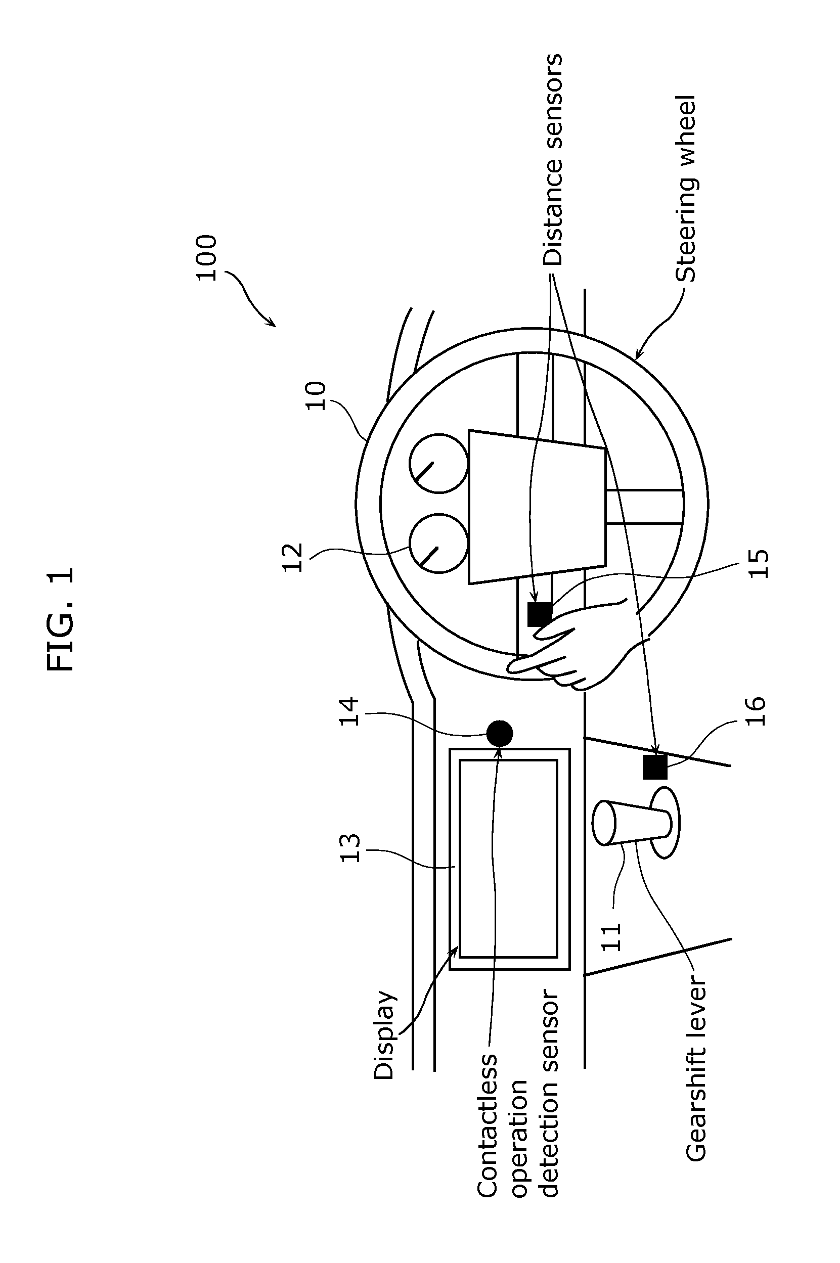
[0041]FIG. 1 is an overview diagram showing a position, in a vehicle, of a vehicular input device according to Embodiment 1 of the present invention.

[0042]As shown in FIG. 1, the vehicle includes a steering wheel 10, a gearshift lever 11, a meter 12, a center display 13, a contactless operation detection sensor 14, plural distance sensors 15 and 16 provided therein.

[0043]The steering wheel 10 is an operation device for a driving operation, for turning wheels to change the traveling direction of a vehicle. The wheels turn right with respect to the traveling direction of the vehicle when a driver turns the steering wheel 10 to the right, and the wheels turn left with respect to the traveling direction of the vehicle when a driver turns the steering wheel 10 to the left.

[0044]The gearshift lever 11 is an operation device for changing gear ratio in a transmission in the case where the vehicle is a manual transmission (MT) vehicle. The gearshift lever 11 is an operation device for changi...

embodiment 2

[0073]FIG. 5 is an overview diagram showing a position, in a vehicle, of a vehicular input device according to Embodiment 2 of the present invention.

[0074]A vehicular input device 200 according to Embodiment 2 has approximately the same configuration as the vehicular input device 100 according to Embodiment 1, and is different from the vehicular input device 100 according to Embodiment 1 in that further including plural contact sensors 17 and 18. Therefore, in the vehicular input device 200 according to Embodiment 2, the same constituent elements as those of the vehicular input device 100 according to Embodiment 1 are denoted by the same reference numerals.

[0075]The following describes a configuration different from that of Embodiment 1, and a description of the same configuration as that of Embodiment 1 will be omitted.

[0076]The contact sensors 17 and 18 (the hatched parts in FIG. 5) are sensors for detecting a contact with an object (for example, a driver's hand), and is either a ...


PUM


Abstract

An object of the present invention is to provide a vehicular input device which is capable of improving accuracy for detecting a contactless input from a driver. A vehicular input device includes a contactless operation detecting unit for detecting a contactless operation on a center display, distance detecting units, distance information storing units in which distance information items obtained from the distance detecting units are stored for each of the distance detecting units, a proximity object determining unit for determining whether or not an object is in proximity of any of predetermined specific positions in a vehicle based on the stored distance information items, and a detecting operation controlling unit for limiting the detection by the contactless operation detecting unit when the object is determined to be in the proximity of any of the specific positions.

Description

TECHNICAL FIELD [0001]The present invention relates to vehicular input devices including displays and vehicular input methods, and particularly to a vehicular input device which is operated through a screen on a display using a contactless operation detection sensor, and a vehicular input method.BACKGROUND ART [0002]On screens of central displays having touch sensors installed in automobiles (hereinafter referred to as “vehicles”), maps for navigation systems or television screens are shown along with operation GUIs including menus and control buttons. However, when users including drivers do not perform operations on the operation screens, the operation GUIs showing necessary information are hidden. In other words, the operation GUIs need not be shown in such a case.[0003]In this regard, a technique has been proposed that a proximity sensor for detecting that an object is in the proximity of the display is disposed in the periphery of a display so that an operation GUI such as a me...

Claims


Application Information

Patent Timeline
Patent Type & Authority Applications(United States)
IPC IPC(8): G06F17/00
CPCB60K37/06G06F3/041G06F17/00B60K2350/928B60K2350/1012B60K2350/925B60K35/00B60K2370/1464B60K2370/791B60K2370/141B60K2370/774B60K2370/782
Inventor KOJIMA, YOSHIHIRONAKANO, NOBUYUKITADA, MASAKI
Owner PANASONIC INTELLECTUAL PROPERTY MANAGEMENT CO LTD
Why Eureka
Try Eureka