Data erasing device using permanent magnet

a data erasing and permanent magnet technology, applied in the field of permanent magnet data erasing devices, can solve the problems of increasing disposal costs, time-consuming data writing, and data erasing processes that did not completely erase all of the data which had been stored on the disk, and achieve the effect of convenient transportation

Inactive Publication Date: 2007-06-19
TOSHIBA STORAGE DEVICE CORP
View PDF11 Cites 1 Cited by
  • Summary
  • Abstract
  • Description
  • Claims
  • Application Information

AI Technical Summary

Benefits of technology

[0022]In the carrying case of the third aspect, the data erasing

Problems solved by technology

Consequently, prior art data erasing processes did not completely erase all of the data which had been stored on the disk.
The method of writing random data on the entire surface of the magnetic disks of the hard disk device as described above has a problem in that writing the data takes time due to the large capacity of the hard disk device, and has an additional problem in that the disposal cost increases when a service organization is asked to erase the data.

Method used


Image

  • Data erasing device using permanent magnet
  • Data erasing device using permanent magnet
  • Data erasing device using permanent magnet

Examples


first embodiment

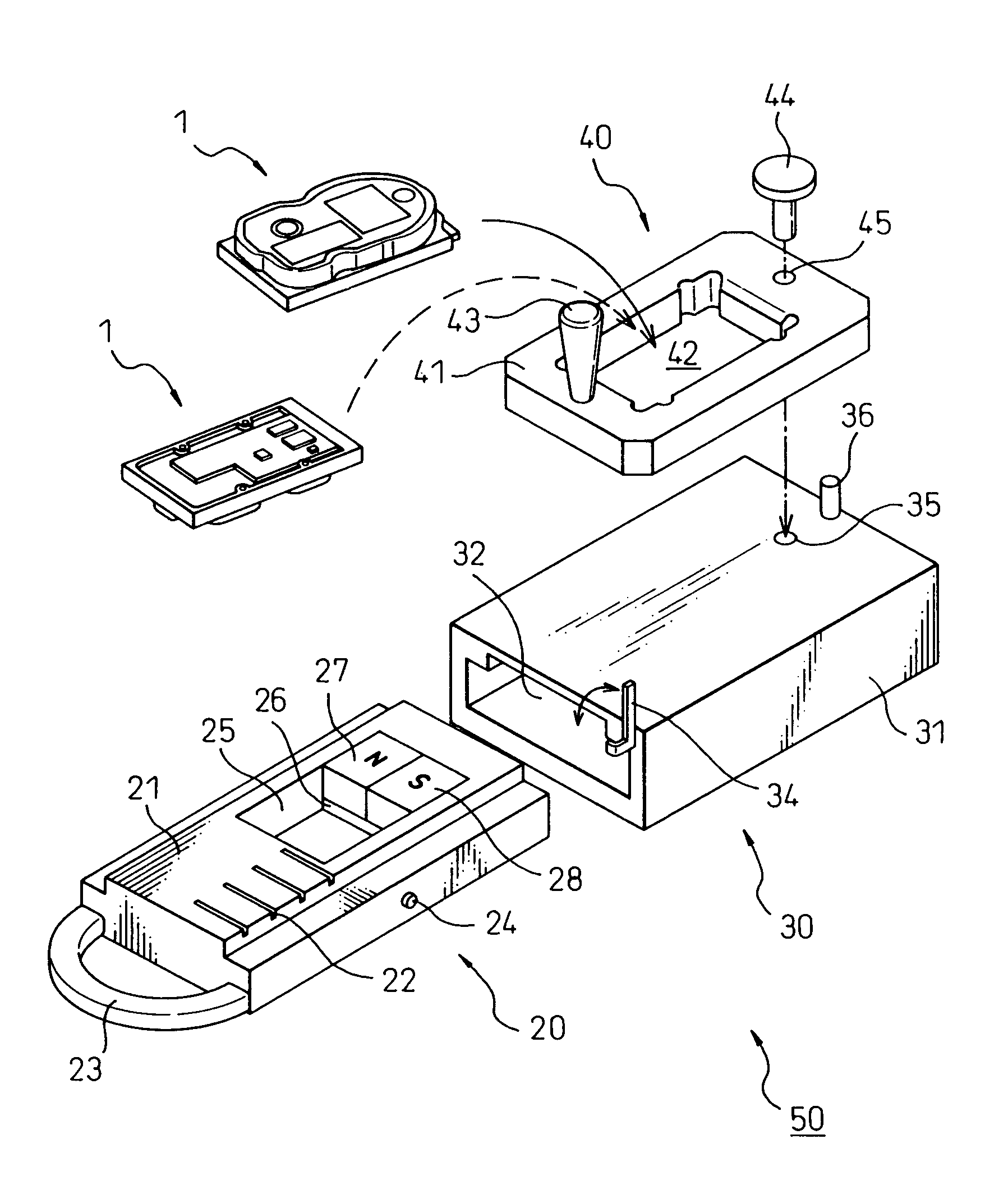
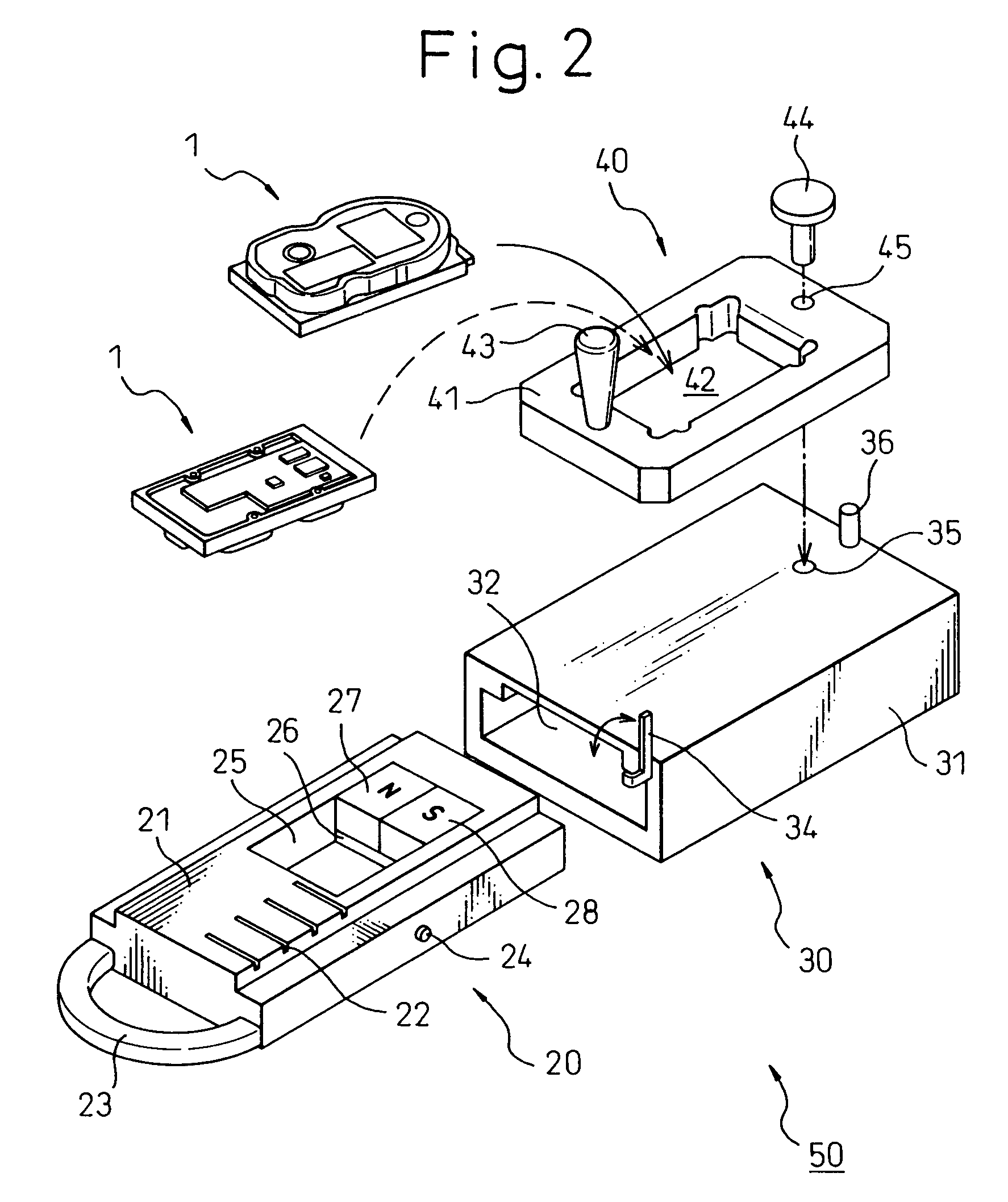
[0053]The sliding tray 20 is constructed so as to be slidable with respect to the main body 30. For this reason, the cross sectional shape of a base 21 in the direction perpendicular to the sliding direction is uniform. A handle 23 for sliding the sliding tray 20 is provided at the front end of the base 21. Grooves 22, to be described later, for defining a stepwise sliding position of the sliding tray 20 are provided on the upper surface at the front end of the base 21 on the handle 23 side. The number of these grooves 22 in the first embodiment is four. Also, a permanent magnet attachment hole 25 is provided in the portion of the base 21 in proximity with and behind the grooves 22. Two permanent magnets (hereafter referred to simply as magnets) 27 and 28 attached to a yoke 26 are provided at the rear of the magnet attachment hole 25. Also, a stopper 24, to be described later, protrudes from the side of the base 21.

[0054]The main body 30 is constructed from a box shaped case 31, wit...

second embodiment

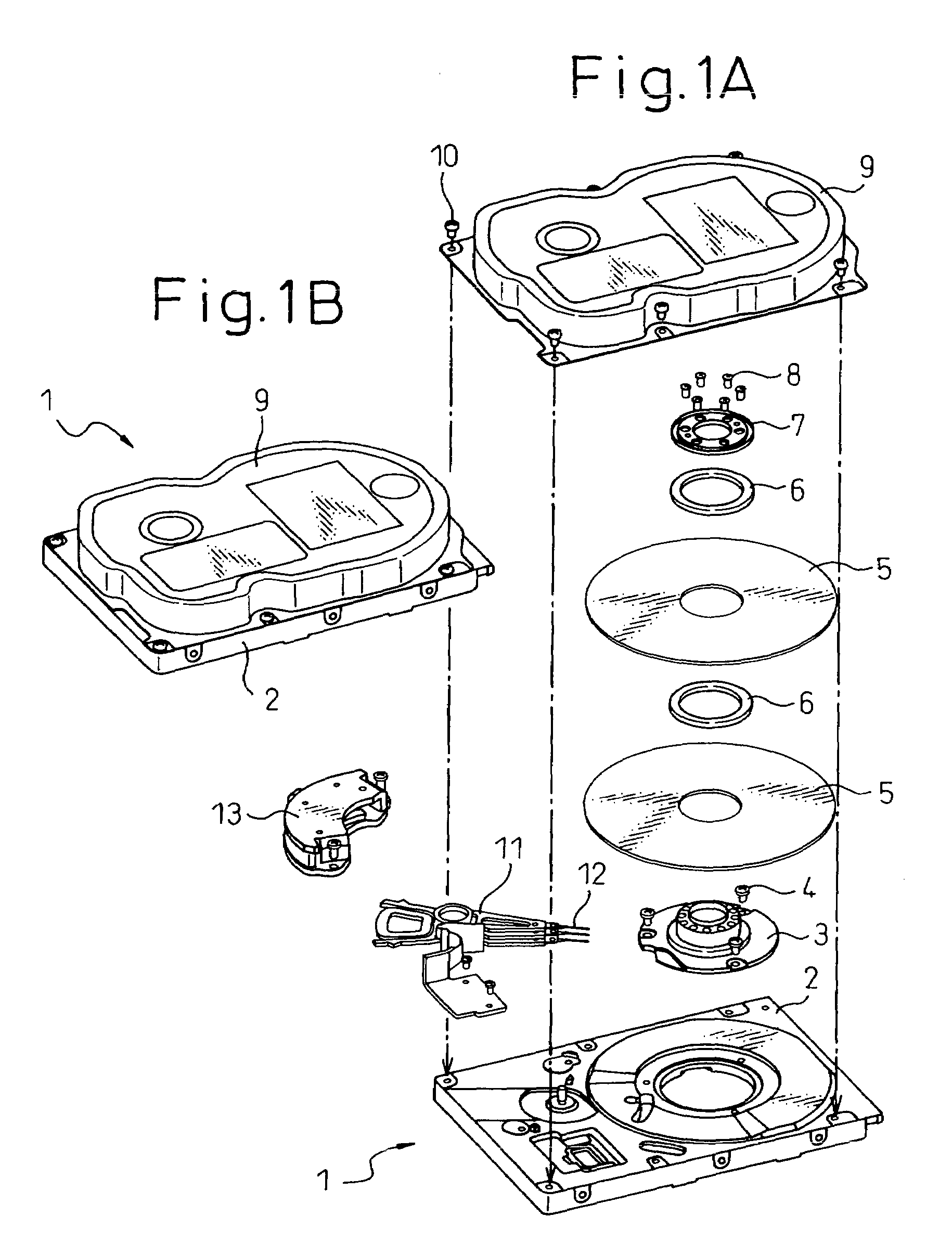
[0081]In the data erasing device 60 of the first aspect of the second embodiment shown in FIG. 10A, the size of the magnets 27 and 28 has been increased and the maximum magnetic flux region M is substantially the same as the diameter D of the magnetic disks 5 in the magnetic disk device 1. Consequently, due to the large sized magnets 27 and 28 the weight of the data erasing device 60 increases, and the cost of the device also increases. In order to solve this problem, as well as decreasing the size of the magnets 27 and 28, the magnets 27 and 28 can be made movable on the case 62 and the number of times that the magnetic disk device 1 is moved into and out of the data erasing device 60 can be increased.

[0082]FIG. 11A illustrates the structure of a modified example of the first aspect of the data erasing device 60 according to the second embodiment of the present invention, in which the size of the magnets 27 and 28 is decreased. In this modified data erasing device 60 the size of th...


PUM


Abstract

In a portable data erasing device, to prevent data leaks from magnetic disk devices to be disposed, data is erased by a simple operation. The data erasing device using a magnetic field generated by permanent magnets to erase data comprises a sliding tray, a main body and a swinging tray. The sliding tray is movable into and out from the main body, two permanent magnets, adjacently arranged so that the north and south poles thereof have mutually attracting polarities, are attached to the front end of the sliding tray. One end of the swinging tray is fixed to the upper surface of the main body by a shaft, so that a magnetic disk device can be mounted and swung on top of the main body. While the sliding tray is extracted stepwise from the main body, the magnetic disk device can be swung, and data on the magnetic disks erased.

Description

CROSS REFERENCE TO RELATED APPLICATION[0001]This application claims priority from, and incorporates by reference the entire disclosure of, Japanese patent application No. 2002-270421, filed on Sep. 17, 2002.BACKGROUND OF THE INVENTION[0002]1. Field of the Invention[0003]The present invention relates to a data erasing device using permanent magnets. In particular, it relates to a portable data erasing device that can easily erase a hard disk device, used in a computer as a memory device, using permanent magnets.[0004]2. Description of the Related Art[0005]In the prior art, in computers such as personal computers and the like, recording media for recording programs and data have become necessary, and in recent years, hard disk devices using a disk coated with a magnetic material have become popular as such recording media. Such hard disk devices are built into the computer or are used as external hard disk devices connected to the computer via a cable, data being written into at least...

Claims


Application Information

Patent Timeline
IPC IPC(8): H01F13/00G11B5/024
CPCG11B5/0245
Inventor HASEGAWA, HIROSHISUZUKI, HISATOUEMATSU, HIROYUKI
Owner TOSHIBA STORAGE DEVICE CORP
Why Eureka
Try Eureka