Apparatus and method for characterizing digital images using a two axis image sorting technique

a two-axis image sorting and image technology, applied in the field of digital image characterization, can solve the problems of specialized operator expertise, lack of effective automation, slow and computationally expensive systems, etc., and achieve the effects of convenient automation, high accuracy, and low cos

Inactive Publication Date: 2007-06-19
CACI MTL SYST INC
View PDF23 Cites 5 Cited by
  • Summary
  • Abstract
  • Description
  • Claims
  • Application Information

AI Technical Summary

Benefits of technology

[0003]The present invention provides an effective, statistics-based characterization technique which is computationally-simple, efficient, accurate, and fast-processing. The vertical and horizontal variations in an image are separated in ord

Problems solved by technology

Unfortunately, such systems are slow and computationally-expensive, involving elaborate and complicated mathematical methods acting upon spatially or spectrally-derived image features.
While prior art systems work acceptably well for certain image characterization applications, they suffer from several disadvantages including

Method used


Image

  • Apparatus and method for characterizing digital images using a two axis image sorting technique
  • Apparatus and method for characterizing digital images using a two axis image sorting technique
  • Apparatus and method for characterizing digital images using a two axis image sorting technique

Examples


second embodiment

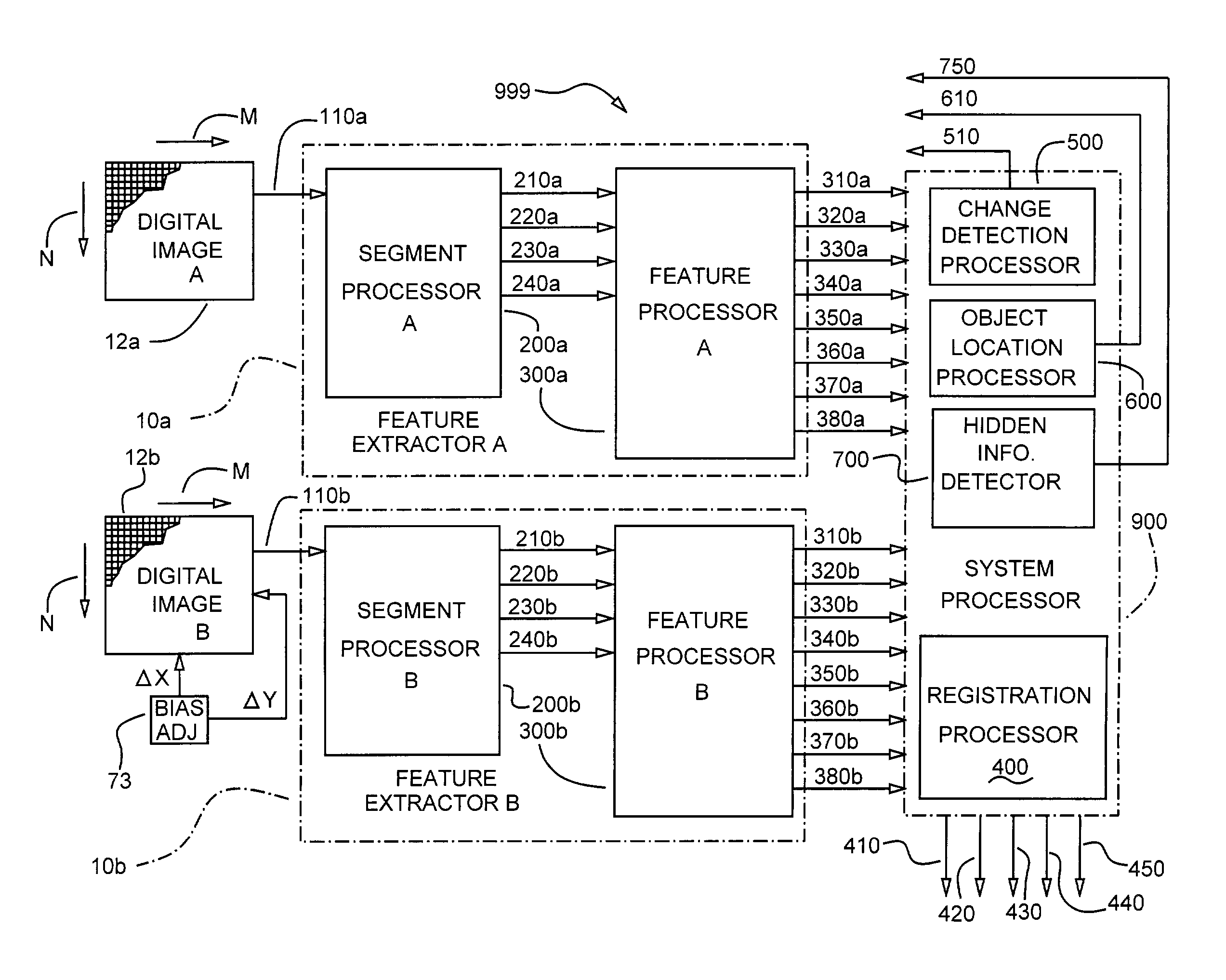
[0035]In the invention the equations for calculating the column and Row Difference Coefficients may take the form:

D(c)=K1[Ma(c,A)−Ma(c,B)]+K2[Da(c,A)−Da(c,B)]+K3[Mt(c,A)−Mt(c,B)]=K4[Dt(c,A)−Dt(c,B)]  {Equation 3}

D(r)=K5[Ma(r,A)−Ma(r,B)]+K6[Da(r,A)−Da(r,B)]+K7[Mt(r,A)−Mt(r,B)]+K8[Dt(r,A)−Dt(r,B)]  {Equation 4}[0036]Where the quantities (K1-K8) are weighting coefficients chosen to suit a particular application of the technique

[0037]Again, there are four variations (V1-V4) on the mathematics, any or all of which may be applied, as follows:[0038]V1: Any or all quantities in brackets [ ] may be converted to absolute values[0039]V2: The Image A and Image B quantities for any or all axis functions may be interchanged, for example, [Ma(c,A)−Ma(c,B)] would become [Ma(c,B)−Ma(c,A)], and so forth[0040]V3: Any or all of the quantities in brackets[ ] may be replaced by a value of 0, eliminating that particular axis function from the calculation[0041]V4: Any or all of the axis functions may be re...

third embodiment

[0042]In the invention the column and Row Difference Coefficients may be calculated by use of the relations:

D(c)=[Ma(c,A) / Ma(c,B)−1][Da(c,A) / Da(c,B)−1][Mt(c,A) / Mt(c,B)−1][Dt(c,A) / Dt(c,B)−1]  {Equation 5}

D(r)=[Ma(r,A) / Ma(r,B)−1][Da(r,A) / Da(r,B)−1][Mt(r,A) / Mt(r,B)−1][Dt(r,A) / Dt(r,B)−1]  {Equation 6}

[0043]Also, with this embodiment there are four variations (V1-V4) on the mathematics, any or all of which may be applied, as follows:[0044]V1: Any or all quantities in brackets [ ] may be converted to absolute values[0045]V2: The Image A and Image B quantities for any or all axis functions may be interchanged, for example, [Ma(c,A) / Ma(c,B)−1] would become [Ma(c,B) / Ma(c,A)−1], and so forth[0046]V2: Any or all of the quantities in brackets [ ] may be replaced by a value of 1.0, eliminating that particular axis function from the calculation[0047]V3: Any or all of the axis functions may be replaced by a normalized version of that axis function, which is calculated by dividing each value in the...

fourth embodiment

[0048]In the invention a weighted sum of quotients is used in the calculation of a Column Difference Coefficient and Row Difference Coefficient calculation for two images, A and B. In that embodiment the column and row Difference Coefficients take the form:

D(c)=K1[Ma(c,A) / Ma(c,B)−1]+K2[Da(c,A) / Da(c,B)−1]+K3[Mt(c,A) / Mt(c,B)−1]+K4[Dt(c,A) / Dt(c,B)−1]  {Equation 7}

D(r)=K5[Ma(r,A) / Ma(r,B)−1]+K6[Da(r,A) / Da(r,B)−1]+K7[Mt(r,A) / Mt(r,B)−1]+K8[Dt(r,A) / Dt(r,B)−1]  {Equation 8}[0049]Where the quantities (K1-K8) are weighting coefficients chosen to suit a particular application of the technique

[0050]Four variations (V1-V4) of this embodiment are:[0051]V1: Any or all quantities in brackets [ ] may be converted to absolute values[0052]V2: The Image A and Image B quantities for any or all axis functions may be interchanged, for example, [Ma(c,A) / Ma(c,B)−1] would become [Ma(c,B) / Ma(c,A)−1], and so forth[0053]V3: Any or all of the quantities in brackets [ ] may be replaced by a value of 0, eliminating...


PUM


Abstract

An automatic digital image characterization system has a feature extractor, including a segment processor and a feature processor. The segment processor is connected for receiving an image in the form of digitized pixel values; each pixel value having an amplitude and being associated with positional information in the form of column and row values. The feature processor converts the image information into column and row axis functions having calculated values of statistical mean amplitude and standard deviation. A system processor registers images, senses image changes, locates objects and detects hidden information.

Description

BACKGROUND OF THE INVENTION[0001]This invention relates to the characterization of digital images and, more particularly, to an apparatus and method for extraction of unique image features through use of statistical mathematics. Image characterization systems have long been used to determine unique features of image content, for many purposes, including image registration, image change detection, locating certain objects in images, and detecting hidden information in images. Unfortunately, such systems are slow and computationally-expensive, involving elaborate and complicated mathematical methods acting upon spatially or spectrally-derived image features. Prior art systems have evolved wherein the operator must have significant expertise in image science, and must manually adjust many parameters of the mathematical processes to achieve satisfactory image characterization for purposes such as those described above.[0002]While prior art systems work acceptably well for certain image ...

Claims


Application Information

Patent Timeline
IPC IPC(8): G06K9/00G06V10/42
CPCG06K9/52G06V10/42
Inventor HILL, RICHARD K.HIRSCH, HERBERT L.
Owner CACI MTL SYST INC
Why Eureka
Try Eureka