Escalator or moving walk

a technology of escalators and moving steps, applied in the direction of conveyors, transportation and packaging, conveyor parts, etc., can solve the problem of long process time for assembly of the complete escalator or moving walk

Active Publication Date: 2007-06-26
INVENTIO AG
View PDF13 Cites 19 Cited by
  • Summary
  • Abstract
  • Description
  • Claims
  • Application Information

AI Technical Summary

Benefits of technology

[0004]The present invention proposes a solution for avoiding the disadvantages of the known construction and permitting the construction of an escalator or moving walk to be carried out in such a manner that assembly operations can be performed in parallel.
[0005]The invention combines head elements into a pre-assembled sub-assembly which can then be mounted on the escalator or moving walk head truss. The sub-assembly may include a pair of comb plate holders to support a comb plate.
[0005]The invention combines head elements into a pre-assembled sub-assembly which can then be mounted on the escalator or moving walk head truss. The sub-assembly may include a pair of comb plate holders to support a comb plate.
[0005]The invention combines head elements into a pre-assembled sub-assembly which can then be mounted on the escalator or moving walk head truss. The sub-assembly may include a pair of comb plate holders to support a comb plate.
[0006]The advantages achieved by the invention include that the process time for assembly of the complete escalator or moving walk can be substantially shortened. In addition, the head elements can be combined into a sub-assembly independent of mounting on the truss and adjusted in advance. The sub-assembly can then be mounted in one piece on the truss of the escalator or moving walk.
[0006]The advantages achieved by the invention include that the process time for assembly of the complete escalator or moving walk can be substantially shortened. In addition, the head elements can be combined into a sub-assembly independent of mounting on the truss and adjusted in advance. The sub-assembly can then be mounted in one piece on the truss of the escalator or moving walk.
[0007]In the further description of a preferred, but nonetheless illustrative embodiment that follows, the invention is presented in relation to an escalator. However, the disclosure also applies analogously to a moving walk, wherein escalator steps 9.1 correspond to moving walk pallets. The listing of the head elements is not exhaustive.

Problems solved by technology

A disadvantage of such a known assembly procedure is that the truss must first be completely assembled before mounting of the head elements can be started, which results in a long process time for assembly of the complete escalator or moving walk.

Method used


Image

  • Escalator or moving walk
  • Escalator or moving walk
  • Escalator or moving walk

Examples


Embodiment Construction

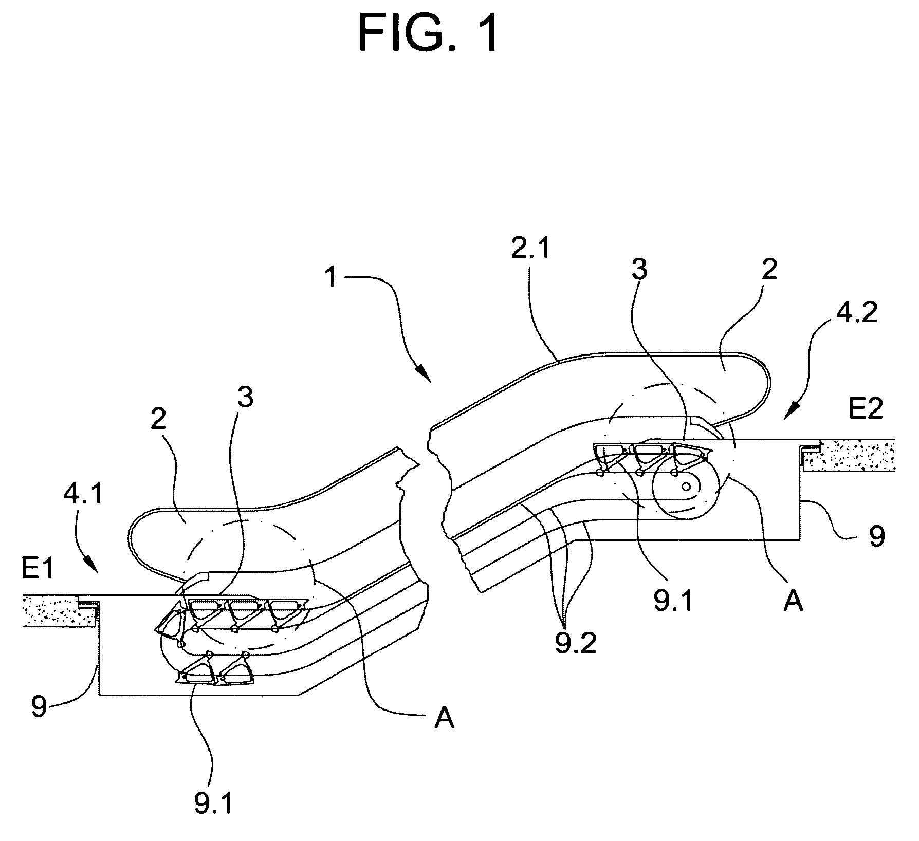
[0017]FIG. 1 shows an escalator 1 with a glass balustrade 2 with handrail 2.1 and, arranged on the lower escalator head 4.1 and on the upper escalator head 4.2, subassemblies 3, each of which comprises individual escalator-head elements and is fastened to the truss 9. The escalator 1 connects a lower floor E1 to an upper floor E2, the steps 9.1 being moved along guides 9.2 of the truss 9.

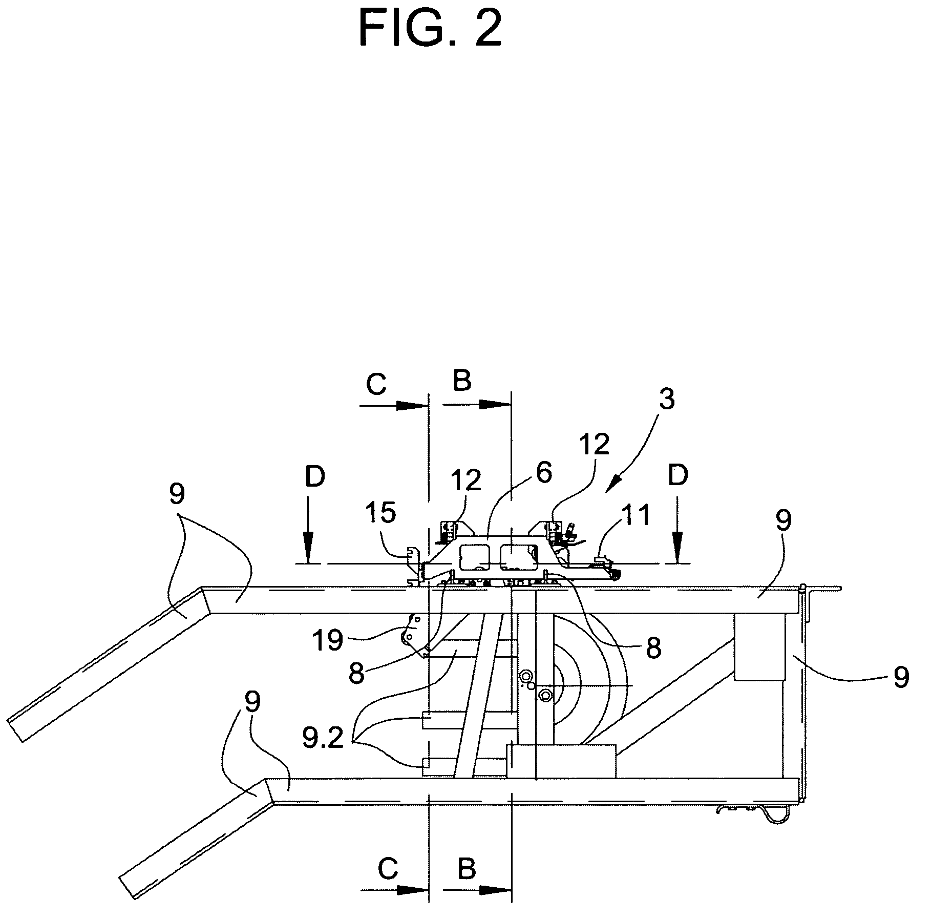
[0018]FIG. 2 details the cutout A of the upper escalator head 4.2 of the escalator 1. FIG. 2 also shows the positions of the cross sections B—B, C—C, and D—D, which are illustrated in FIGS. 4, 5 and 3, respectively.

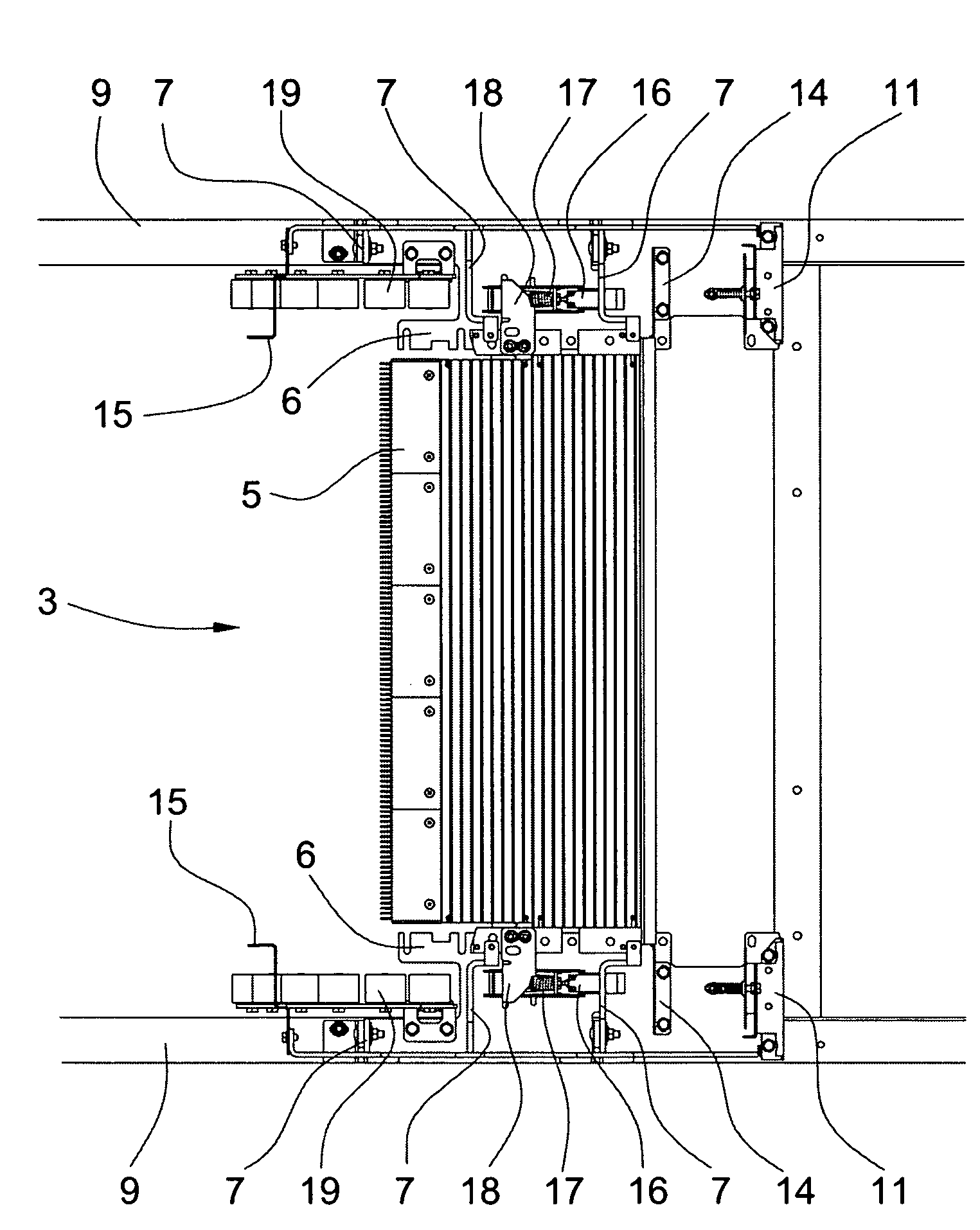
[0019]As seen, the subassembly 3 essentially includes a comb-plate holder or carrier 6 on each side, which together carry a comb plate 5. Each comb-plate carrier has a C-shaped profile and is reinforced by stiffening ribs 7 so as to bear the weight of the end-curve of the glass balustrade 2. The stiffening ribs 7 are, for example, welded to the comb-plate carrier 6. By means of supports 8...


PUM


Abstract

An improved escalator or moving walk construction, head elements are pre-assembled as a sub-assembly which is subsequently mounted on the truss of the escalator. The sub-assembly includes comb plate holders, one on each side, which carry a comb plate. The comb plate holder may have a C-shaped profile and may be reinforced by stiffening ribs so as to be able to bear the weight of the end-curve of a balustrade. By means of supports arranged on the truss, the height of the comb plate carrier can be adjusted to that of the truss. During pre-assembly, and until after final mounting on the truss, the comb plate serves as a connecting element between comb plate holders.

Description

[0001]The invention relates to an escalator or moving walk with steps or pallets, a balustrade with handrail, and head elements arranged on a lower escalator head or moving-walk head and on an upper escalator head or moving-walk head, that are connected to a truss of the escalator or moving walk.BACKGROUND OF THE INVENTION[0002]Head elements such as, for example, comb plates, balustrade clips, skirt-panel fastening brackets, handrail return sheaves, finger-protection mechanisms, and the like of an escalator or moving walk are usually mounted on the escalator or moving walk truss, and are adjusted individually.[0003]A disadvantage of such a known assembly procedure is that the truss must first be completely assembled before mounting of the head elements can be started, which results in a long process time for assembly of the complete escalator or moving walk.[0004]The present invention proposes a solution for avoiding the disadvantages of the known construction and permitting the con...

Claims


Application Information

Patent Timeline
Patent Type & Authority Patents(United States)
IPC IPC(8): B66B23/00
CPCB66B23/00B66B29/06
Inventor ILLEDITS, THOMASULRICH, ROBERTHOLZL, HUBERT
Owner INVENTIO AG
Why Eureka
Try Eureka