Lock with remotely activated lockout feature

Inactive Publication Date: 2007-06-26
INC SMARTLOK SYST
View PDF26 Cites 87 Cited by
  • Summary
  • Abstract
  • Description
  • Claims
  • Application Information

AI Technical Summary

Problems solved by technology

A remotely controllable lockout assembly, however, is capable of over locking the storage unit so that the renter can no longer gain entry when the lockout assembly is activated.

Method used


Image

  • Lock with remotely activated lockout feature
  • Lock with remotely activated lockout feature
  • Lock with remotely activated lockout feature

Examples


Embodiment Construction

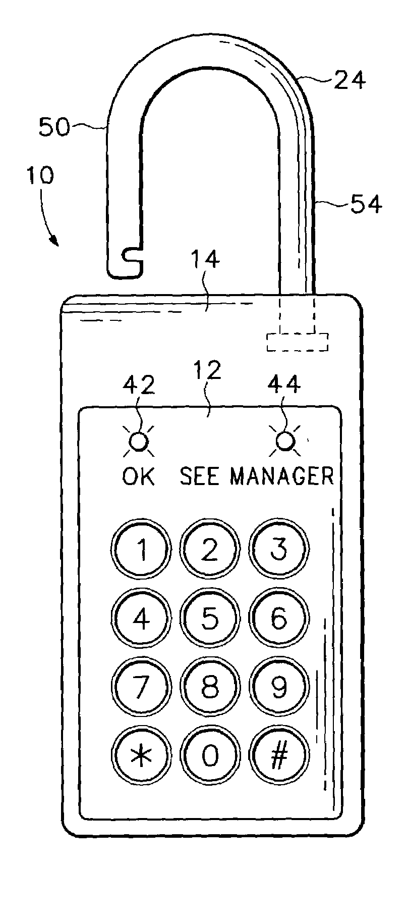
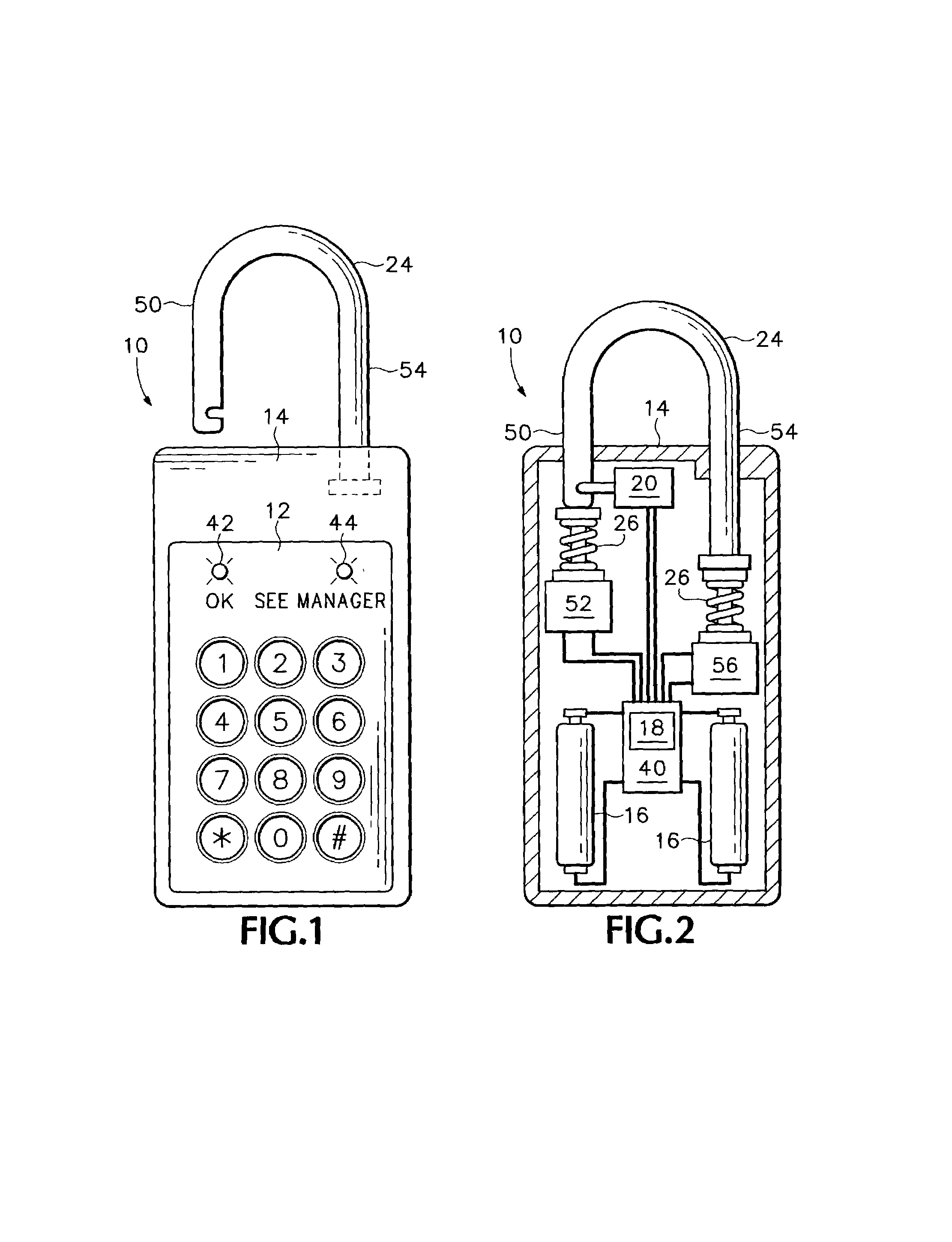
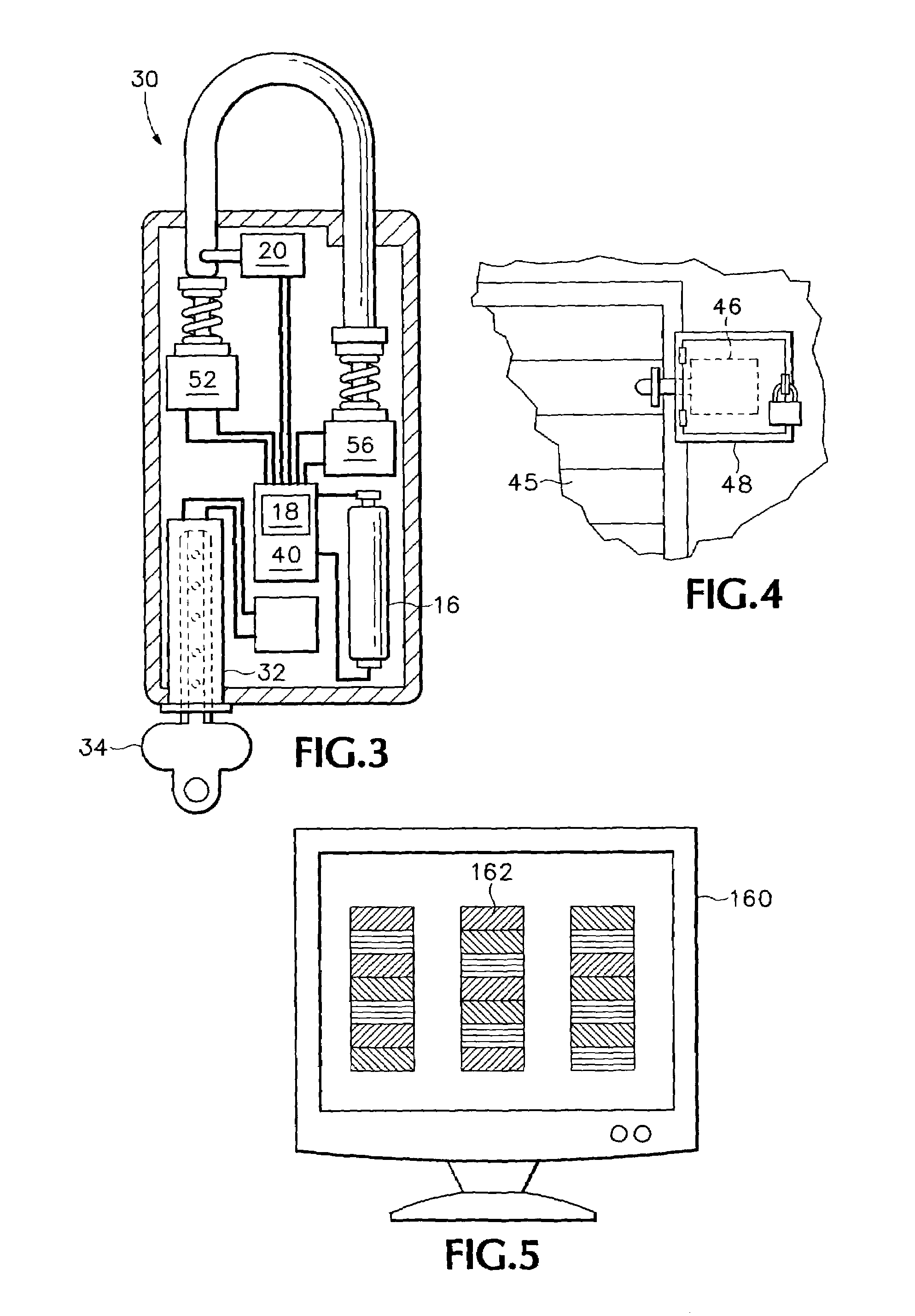
[0018]Referring to FIGS. 1 and 2, a first preferred embodiment of the present invention takes the form of a combination lock 10, having a keypad 12, on the face of a lock body 14, adapted to accept and recognize a combination entered by a user. Keypad 12 is preferably a water-tight membrane dome type. The recognition task requires electric power, which is provided by a pair of batteries 16. If the entered code matches a set code in a logic mechanism 18 and if the lock is in user controlled state (see below), a solenoid 20 retaining a shackle 24 is placed in a state that permits shackle 24 to be pulled outwardly from body 14, thereby freeing a shorter leg 50 of the shackle 24. Springs 26 urge the shackle 24 upwards into an open state. In a second preferred embodiment the lock (FIG. 3) is an electronic key lock 30 that uses a magnetic key reader 32 to read a magnetically encoded key 34. The following disclosure applies to lock 30 as well as lock 10 with all references to a “combinatio...


PUM


Abstract

A method for controlling access to a storage unit owned by an owner, wherein a renter has access to the storage unit unless the owner receives the legal right to deny the renter access to the storage unit and decides to do so. In this method, the storage unit is secured by a lock that is, at least in part, controlled by the renter. A remotely controllable lockout assembly, however, is capable of over locking the storage unit so that the renter can no longer gain entry when the lockout assembly is activated. The method includes remotely controlling the lockout assembly to deny the renter access to the unit when the owner receives the legal right to deny the renter access to the storage unit and decides to do so.

Description

BACKGROUND OF THE INVENTION[0001]Self-storage units, in the United States, are typically rented on a monthly basis with the rent for each month being due on the first day of that month. If the rent is not paid by the tenth day of the month, the owner of the facility gains the legal right to lock out the renter, so that the renter no longer has access to the storage unit. Accordingly, on the eleventh day of each month, the manager of a self-storage facility typically has the task of walking around the facility and over locking all of the units for which the renter of the unit has not paid his rent for the current month. This is done by placing an additional lock on the storage unit door, through a hasp specially set for this purpose. For a large facility with hundreds of storage units this task can take two to four hours.[0002]Another characteristic of self-storage facilities is that they are typically fenced and gated. The gate is controlled by a keypad that is linked to a computer....

Claims


Application Information

Patent Timeline
Patent Type & Authority Patents(United States)
IPC IPC(8): H04Q9/00E05B65/52E05G1/00
CPCE05B45/005E05B47/02E05B47/0603E05G1/00E05G1/04G06Q10/087G06Q20/20G06Q20/206G06Q30/016G06Q30/0645G07C9/00571G07C9/00896E05B47/0002E05B65/0021E05B73/00E05B2047/0094G07C9/00166Y10T70/7068Y10T70/5031G07C9/38
Inventor ARONSON, GLEN L.WOLLAM, JOHN
Owner INC SMARTLOK SYST
Why Eureka
Try Eureka