Conductors for electro-dynamic loudspeakers

a technology of electro-dynamic loudspeakers and capacitors, which is applied in the direction of loudspeakers, diaphragm construction, transportation and packaging, etc., can solve the problems of not being able to position or orient the desired loudspeaker, and being difficult to achieve the desired performance of the audio system

Active Publication Date: 2007-06-26
HARMAN INT IND INC
View PDF56 Cites 7 Cited by
  • Summary
  • Abstract
  • Description
  • Claims
  • Application Information

AI Technical Summary

Problems solved by technology

Many design and manufacturing challenges present themselves in the manufacturing of electro-dynamic loudspeakers.
Accordingly, designing conductors for electro-dynamic loudspeaker applications presents various challenges such as selecting the speaker with the desired audible output for a given location that will fit within the size and location constraints of the desired applications environment.
Often, space limitations in the listening environment prohibit the use of a loudspeaker in an audio system that possesses the preferred directivity pattern for the system's design.
For example, the amount of space and the particular locations available in a listening environment for locating and / or mounting the loudspeakers of the audio system may prohibit the use of a particular loudspeaker that exhibits the intended directivity pattern.
Also, due to space and location constraints, it may not be possible to position or oriented the desired loudspeaker in a manner consistent with the loudspeaker's directivity pattern.
Consequently, size and space constraints of a particular environment may make it difficult to achieve the desired performance from the audio system.
Unfortunately, the large rectangular size results in a high-frequency beam width angle or coverage that may be too narrow for its intended application.
The frame presents design challenges since it is preferably rigid enough to keep the diaphragm film tension uniform and capable of not deforming during handling, assembly, or over time.
The final assembly may be mounted on a vehicle, and therefore, must be rigid during shipping and handling and should not allow the diaphragm or frame to deform during installation.

Method used


Image

  • Conductors for electro-dynamic loudspeakers
  • Conductors for electro-dynamic loudspeakers
  • Conductors for electro-dynamic loudspeakers

Examples


Embodiment Construction

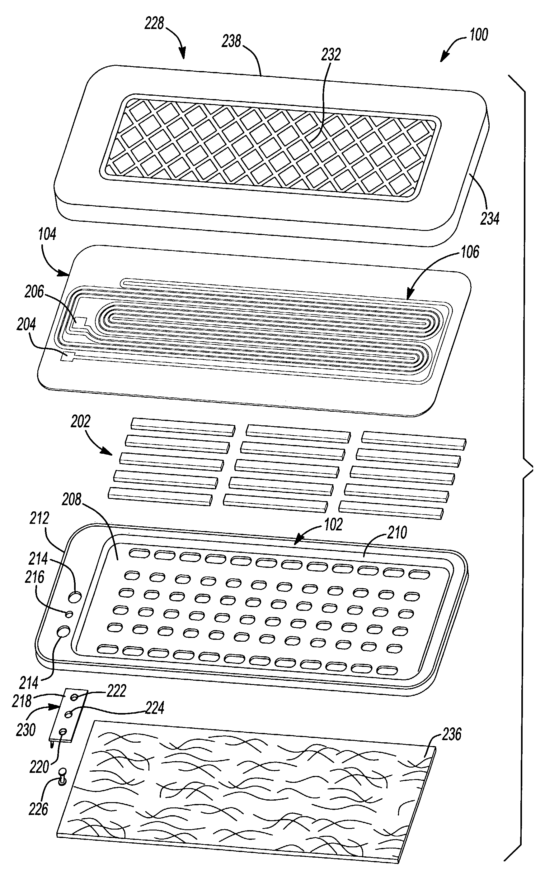
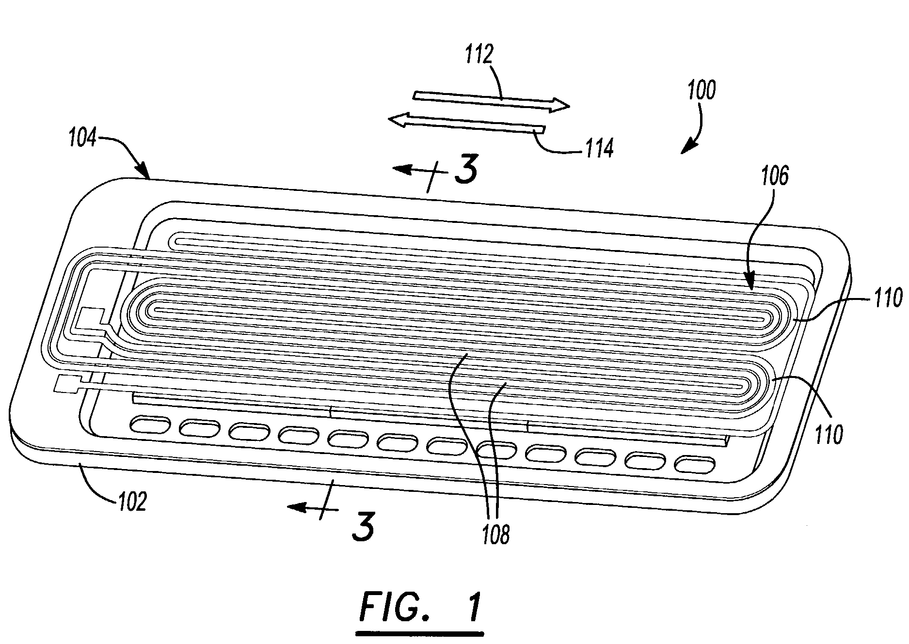
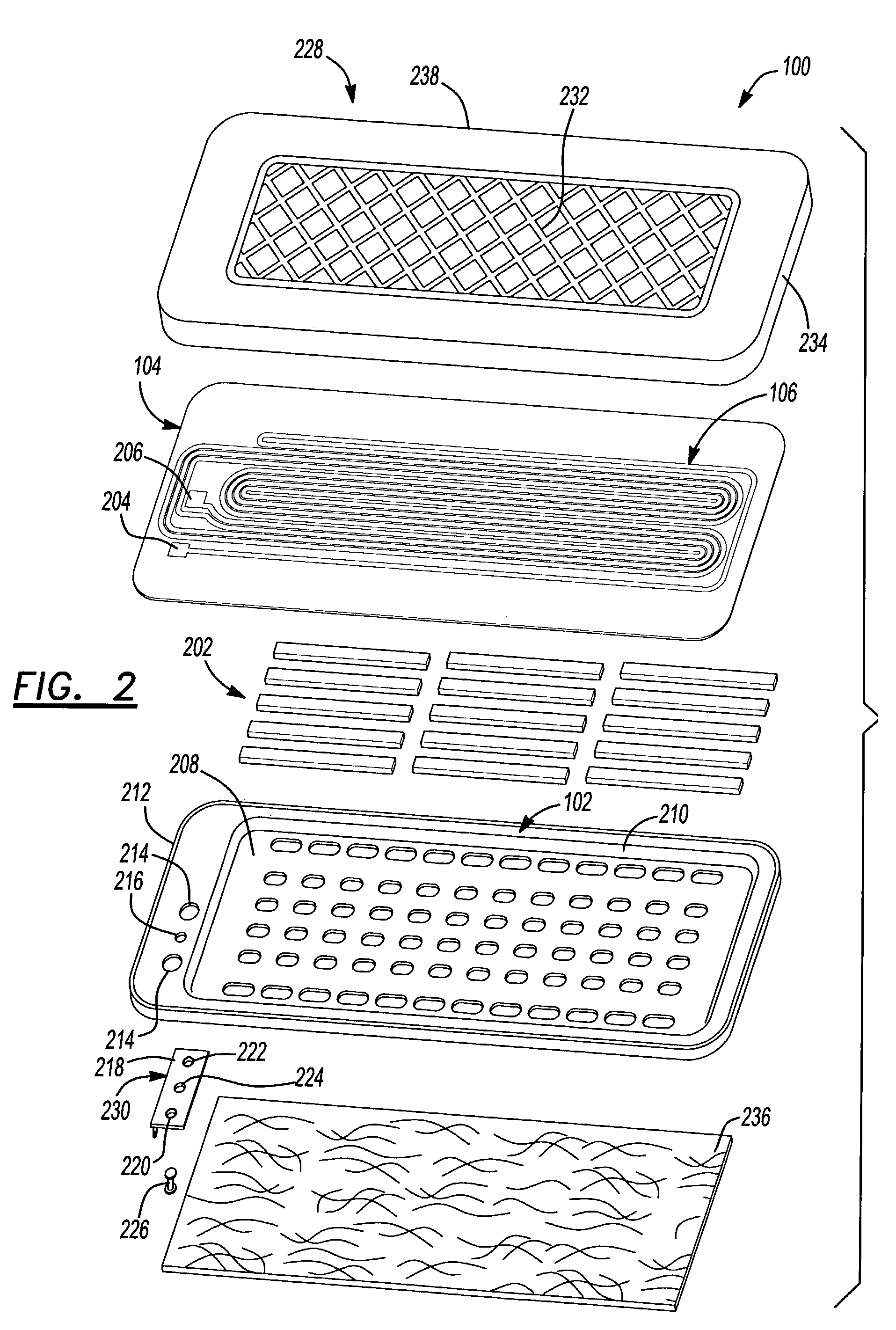
[0046]FIG. 1 is a perspective view of an electro-dynamic loudspeaker 100 of the invention. As shown in FIG. 1, the electro-dynamic loudspeaker is a generally planar loudspeaker having a frame 102 with a diaphragm 104 attached in tension to the frame 102. A conductor 106 is positioned on the diaphragm 104. The conductor 106 is shaped in serpentine fashion having a plurality of substantially linear sections (or traces) 108 longitudinally extending along the diaphragm interconnected by radii 110 to form a single current path. Permanent magnets 202 (shown in FIG. 2) are positioned on the frame 102 underneath the diaphragm 104, creating a magnetic field.

[0047]Linear sections 108 are positioned within the flux fields generated by permanent magnets 202. The linear sections 108 carry current in a first direction 112 and are positioned within magnetic flux fields having similar directional polarization. Linear sections 108 of conductor 106 having current flowing in a second direction 114, th...


PUM


Abstract

Electro-dynamic loudspeakers typically include a diaphragm that is secured to a frame and has a conductor applied to at least one surface of the diaphragm. The conductor is connected to a power amplifier for providing electric current through the linear traces of the conductor that interact with magnetic fields generated by magnets that are mounted to the frame. The interaction between the current passing through the conductor and the magnetic fields cause vibration in the diaphragm that creates the sound that is heard from the electro-dynamic loudspeaker. Different methodologies of forming the conductor are provided for simplifying the manufacturing process and for locating the conductor closer to the magnetic field generated by the magnets.

Description

CROSS REFERENCE TO RELATED APPLICATIONS[0001]This application claims the benefit of U.S. Provisional Application Nos. 60 / 380,001, filed May 2, 2002, 60 / 378,188, filed May 6, 2002, and 60 / 391,134, filed Jun. 24, 2002, and is incorporated by reference.CROSS REFERENCE TO CO-PENDING APPLICATIONS[0002]This application incorporates by reference the disclosures of each of the following co-pending applications which have been filed concurrently with this application: U.S. patent application Ser. No. 10 / 428,313, entitled “Mounting Bracket System,” filed May 2, 2003; U.S. patent application Ser. No. 10 / 429,165, entitled “Film Tensioning System,” filed May 2, 2003; U.S. patent application Ser. No. 10 / 428,316, entitled “Film Attaching System,” filed May 2, 2003; U.S. patent application Ser. No. 10 / 429,228, entitled “Electrical Connectors For Electro-Dynamic Loudspeakers,” filed May 2, 2003; U.S. patent application Ser. No. 10 / 428,314, entitled “Electro-Dynamic Loudspeaker Mounting System,” file...

Claims


Application Information

Patent Timeline
Patent Type & Authority Patents(United States)
IPC IPC(8): H04R25/00B60R11/02H04R1/02H04R1/06H04R5/02H04R7/04H04R7/18H04R9/00H04R9/02H04R9/04H04R9/06H04R11/02H04R31/00
CPCB60R11/0223H04R1/06H04R9/025H04R9/047H04R31/006B60R11/0217H04R1/025H04R1/026H04R7/04H04R7/18H04R9/06H04R31/003H04R2201/34H04R2400/11H04R2499/13
Inventor GARNER, DAVID B.
Owner HARMAN INT IND INC
Why Eureka
Try Eureka