

Conference call method and apparatus therefor
- Summary
- Abstract
- Description
- Claims
- Application Information
AI Technical Summary
Benefits of technology
Problems solved by technology
Method used
Image

Examples
Embodiment Construction
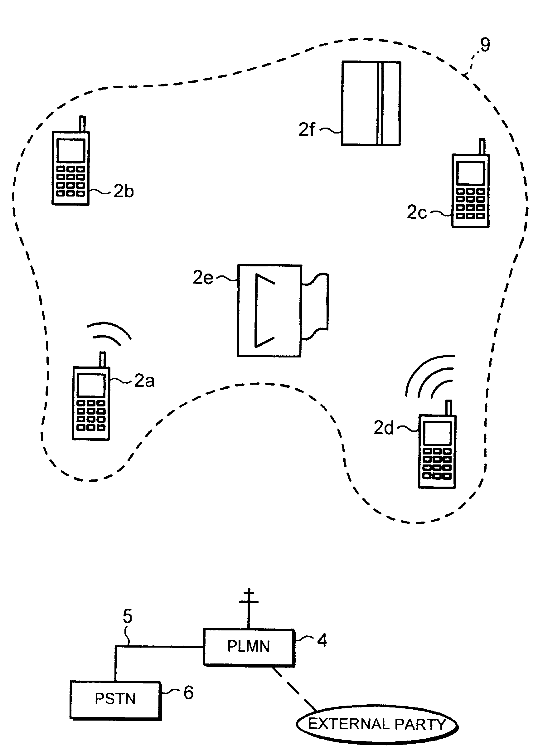
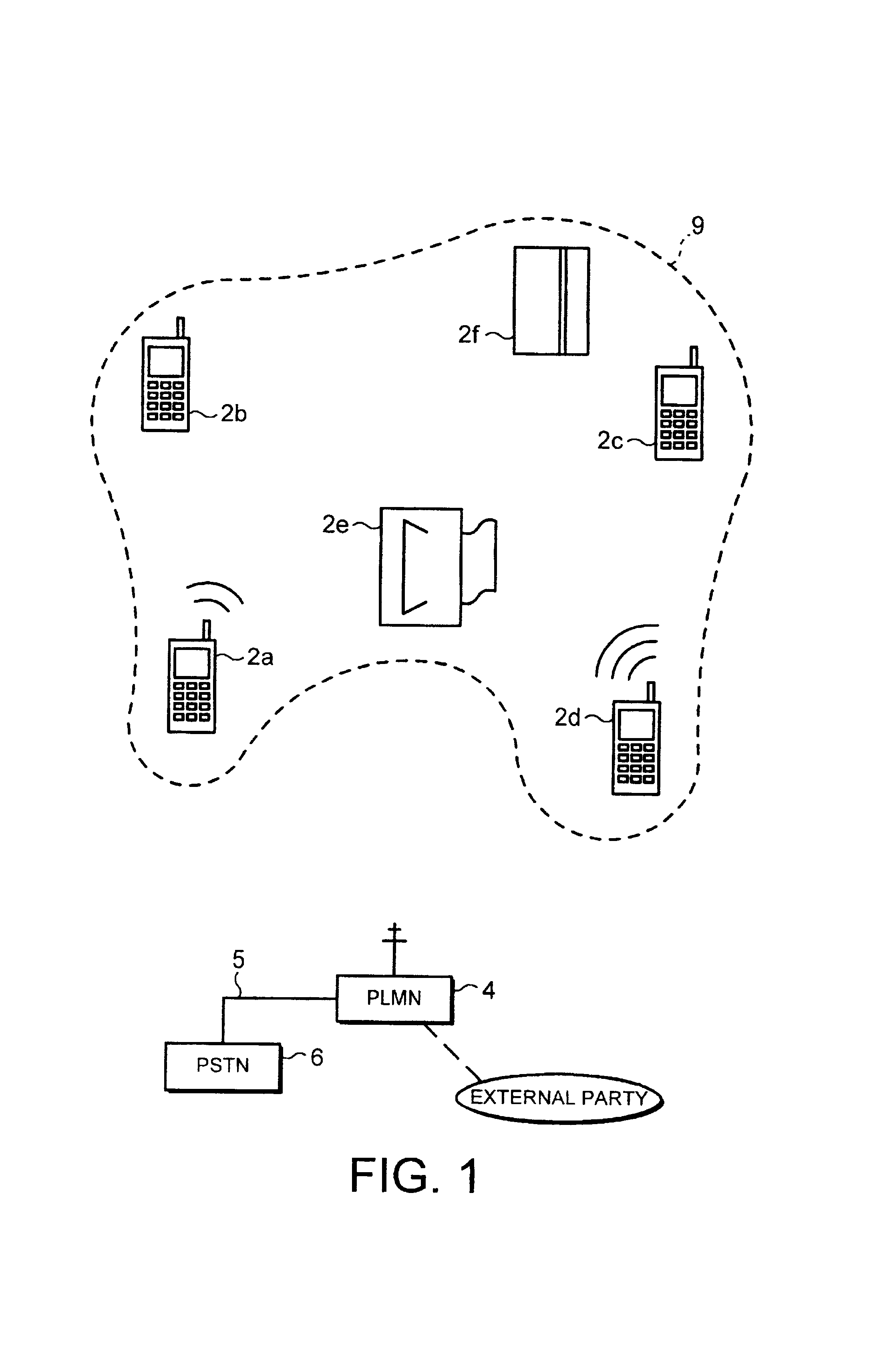
[0019]Referring to the Figures, there is shown a collection of devices each equipped with a LPRF module 1 (see FIG. 3). The devices include a number of cellular radio telephones 2a,2b,2c,2d. As is well known, each radio telephone or mobile station 3 forms part of a public land mobile network (PLMN) 4 which through various gateways 5 may in itself be linked to other networks such as a PSTN 6.
[0020]Referring to FIG. 3, there is shown a communication device namely a radio telephone 2a including the well known baseband 10a, RF 10b, and processor 10c components which together permit the telephone to operate within the PLMN. The telephone 2a further includes the LPRF module 1 that contains a radio unit 7 that provides an air interface that complies with Federal Communications Commission (FCC) rules for the Industrial, Scientific and Medical (ISM) band at power levels up to 0 dBm. The interface operates in a frequency-hopping mode that results in a spread spectrum operation in the range of...
PUM
 Abstract
Description
Claims
Application Information