
Tub overflow assembly

Inactive Publication Date: 2007-07-03
KEENEY HLDG LLC
View PDF21 Cites 34 Cited by
  • Summary
  • Abstract
  • Description
  • Claims
  • Application Information

AI Technical Summary

Benefits of technology

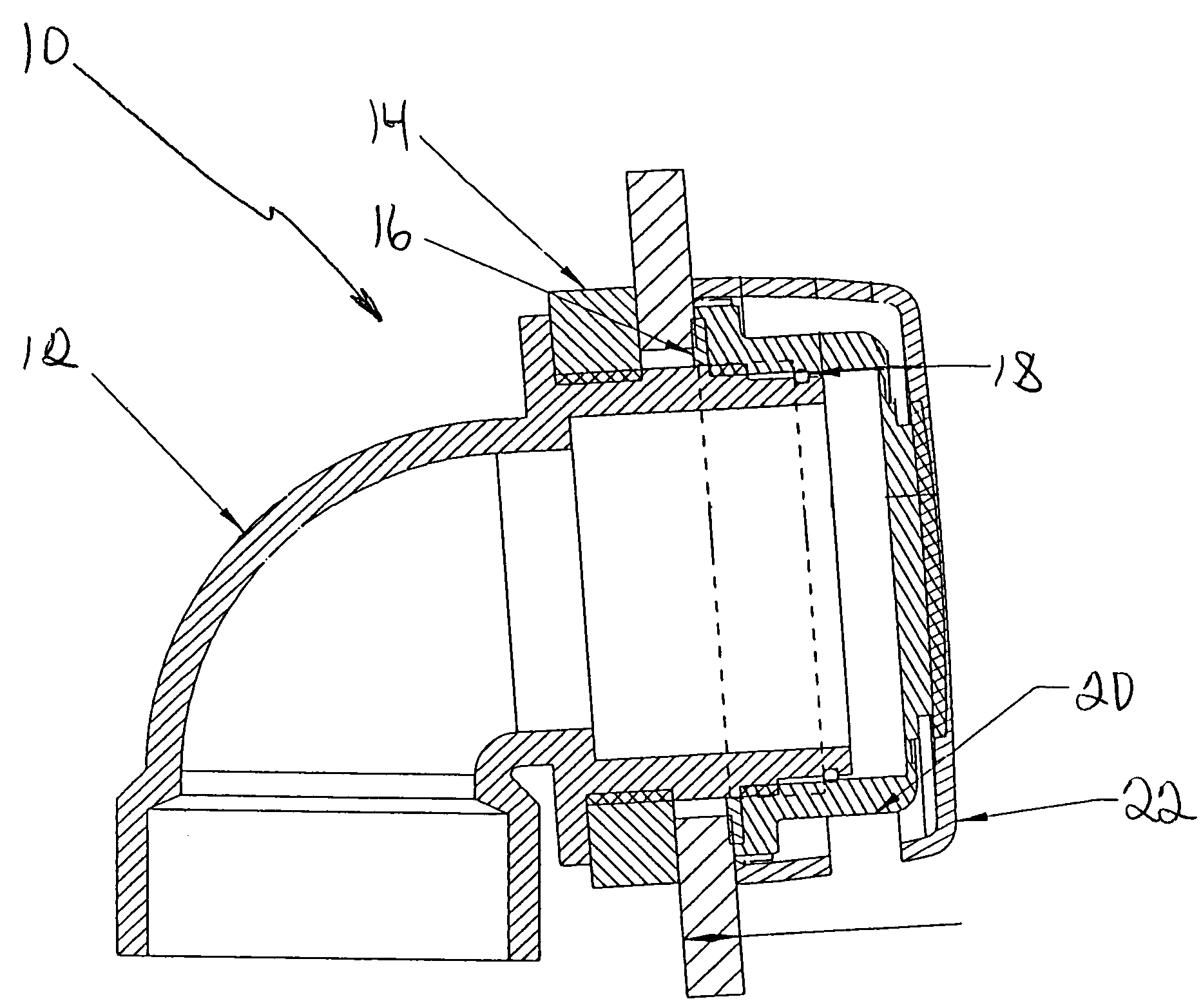
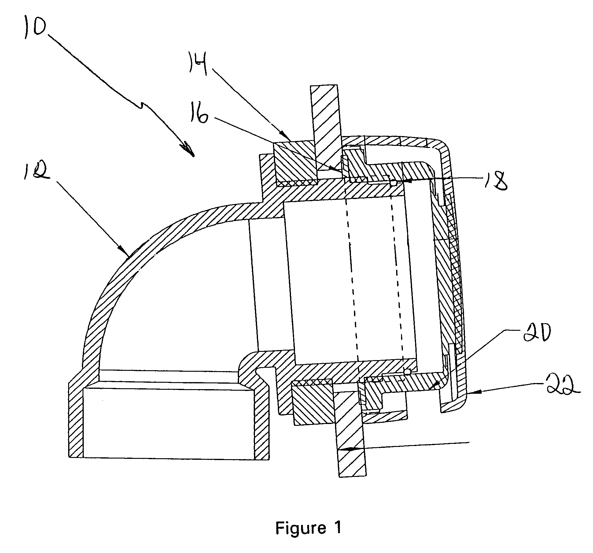
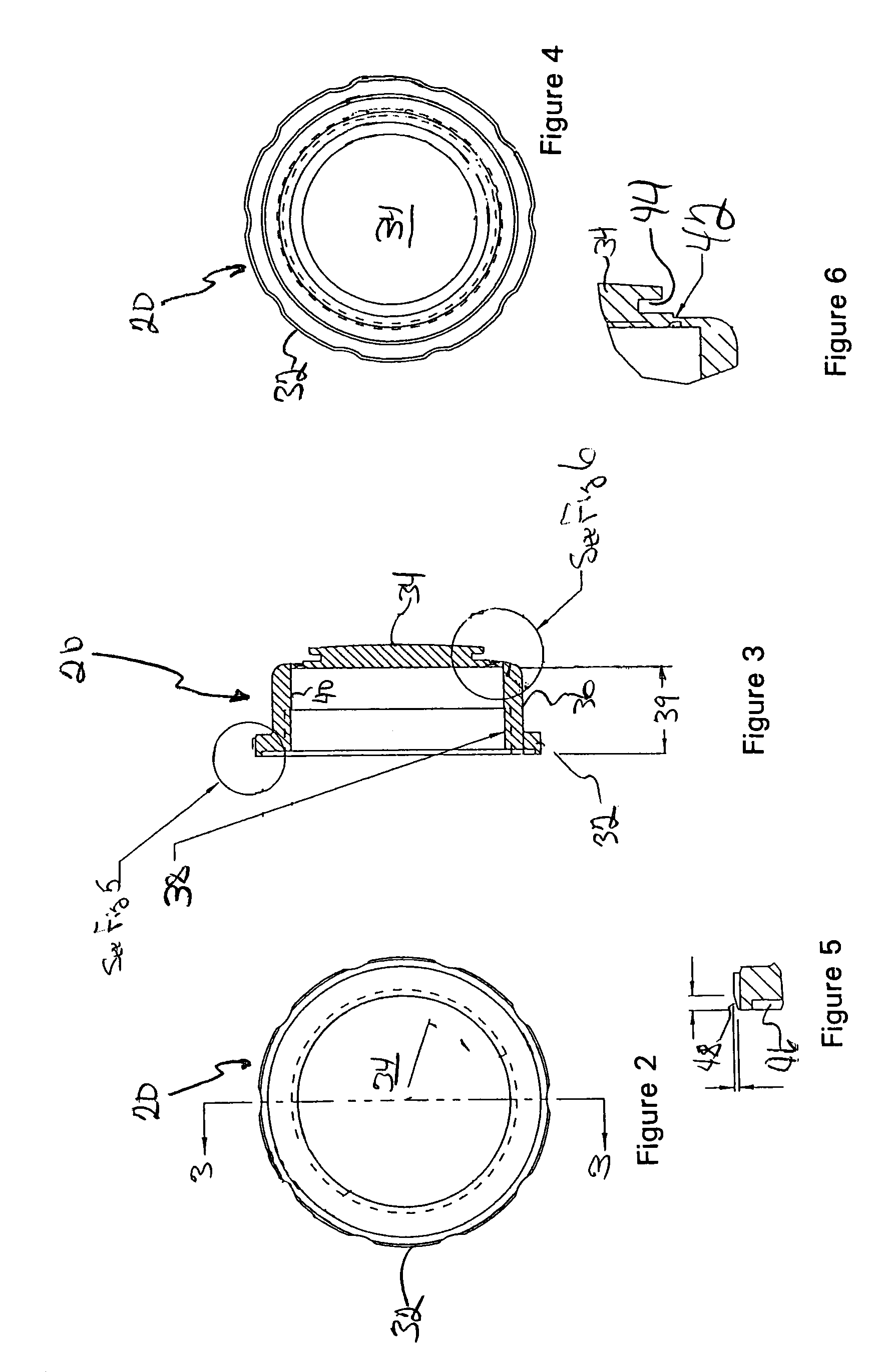
[0010]The present invention employs an overflow elbow having an externally threaded cylindrical fitting that extends integrally through the tub overflow opening. An internally threaded retainer nut with integrally molded test cap is threadably engaged with the overflow cylindrical fitting to compress gaskets against both the inside and outside surfaces of the tub. The test cap is integrally molded with the retainer nut with a thin, breakable connection between the nut and cap. An undercut lip on the test cap facilitates use of a prying tool to break the thin connection and remove the test cap after testing of the drain plumbing.
[0011]The tub overflow assembly includes an overflow elbow, an outside gasket, an inside gasket, an o-ring seal, the integrated retainer nut and test cap and a trim cap. The outside gasket is a thick sponge type gasket configured for compression between a radially extending flange of the overflow elbow and the outside surface of the tub around the overflow opening. The inside gasket is a flat rubber gasket that is compressed between one end of the retainer nut and the inside surface of the tub around the overflow opening. The retainer nut is configured with a channel or seat for the inside gasket. The inside gasket prevents water from escaping from behind the retainer nut and through the overflow opening. The outside gasket is configured to stop any water that may get past the inside gasket.
[0012]The overflow elbow includes a cylindrical fitting configured to extend through the tub overflow opening and into the tub. The cylindrical fitting has a generally cylindrical outside surface with a threaded section and an unthreaded section including a groove that receives an o-ring seal. The threaded section of the cylindrical fitting outside surface is adjacent the flange and the unthreaded section extends from the threaded section. The retainer nut has a generally cylindrical configuration complementary to the cylindrical fitting. The retainer nut inside surface is partially threaded and partially unthreaded. The unthreaded portion of the retainer nut inside surface is configured to radially compress and seal against the o-ring seal retained in the groove defined by the cylindrical fitting unthreaded section. The depth of the inside surface of the retainer nut and the overlapping cylindrical configuration of the overflow elbow and retainer nut and test cap accommodate variations in the thickness of the bathtub wall.

Problems solved by technology

One potential drawback to this approach is that the thin diaphragm can be damaged during manufacture, shipping or installation of the overflow assembly.
Manufacture and packaging of separate retainer nuts and test caps is costly and presents the potential that one or the other may be omitted from the packaged assembly.
A potential drawback of the '331 overflow assembly structure is that the threaded joint between the overflow cap and the overflow elbow is positioned outside the tub.
This presents the potential for leakage that is not present in an overflow elbow configured to extend integrally through the tub overflow opening.

Method used


Image

  • Tub overflow assembly
  • Tub overflow assembly
  • Tub overflow assembly

Examples


Embodiment Construction

[0031]The inventive overflow assembly will now be described with reference to FIGS. 1–17. FIG. 1 is a vertical sectional view through the six components of the overflow assembly 10. The overflow assembly includes the overflow elbow 12, an outside gasket 14, an inside gasket 16, an o-ring seal 18, a retainer nut with integrally molded test cap 20, and a trim cap 22.

[0032]The overflow elbow 12 is molded from PVC or ABS plastic for compatibility with the plastic employed in the remainder of the drain plumbing system. The overflow elbow 12 extends from a lower end portion defining a socket 24 configured to receive standard plastic pipe to an upper end portion including a cylindrical fitting 26 configured to extend into a bathtub through the tub overflow opening. The overflow elbow 12 is so called because of its inverted L-shape, which provides a flow passage extending downwardly to facilitate connection of the tub overflow opening with the bathtub drain. A flange 28 radially projects fr...


PUM


Abstract

An overflow assembly employs an overflow elbow having an externally threaded cylindrical fitting that extends through the tub overflow opening. An internally threaded retainer nut with integrally molded test cap is threadably engaged over the overflow elbow cylindrical fitting to compress gaskets against both the inside and outside surfaces of the tub. A test cap is integrally molded with the retainer nut and joined to the retainer nut by a thin, breakable connection. An undercut lip on the test cap facilitates use of a prying tool to break the thin connection and remove the test cap after testing of the drain plumbing. A trim cap snaps over the retainer nut to provide a finished appearance to the installed overflow assembly.

Description

BACKGROUND OF THE INVENTION[0001]1. Field of the Invention[0002]The invention relates generally to bathtub overflow assemblies and more particularly to an overflow assembly equipped with a test cap to permit pressure testing of the waste plumbing during construction.[0003]2. Description of the Related Art[0004]In new construction, plumbers are required to test the assembled waste or drain plumbing of a structure before closure of wall and ceiling surfaces. Such testing is performed under pressure to detect leaks or flaws in the waste plumbing system so that such leaks are repaired while the plumbing is still easily accessible.[0005]Bathtub overflow assemblies are well-known plumbing fixtures that connect the overflow opening of a bathtub to the bathtub drain. The overflow opening in the bathtub is typically positioned on an end wall of the bathtub at a pre-selected elevation to limit the maximum level of water in the tub and prevent bathtub overflow. Water above the level of the ove...

Claims


Application Information

Patent Timeline
IPC IPC(8): E03C1/22E03C1/244
CPCE03C1/24E03C2001/2413
Inventor HOLDEN, JR., R. STUARTGRAHAM, CHRISPIETERS, FRANK
Owner KEENEY HLDG LLC
Learn More