System and method for reducing power consumption in digital radiography detectors

a radiography detector and power consumption technology, applied in the field of portability of health care imaging devices, can solve the problems of increasing the amount of heat energy generated by the components of medical devices, reducing the life of batteries, and reducing the effect of power consumption

Inactive Publication Date: 2007-07-03
GENERAL ELECTRIC CO
View PDF2 Cites 43 Cited by
  • Summary
  • Abstract
  • Description
  • Claims
  • Application Information

AI Technical Summary

Problems solved by technology

However, the requirements necessary to achieve portability result in severe constraints on space, weight and power dissipation causing an increase in the amount of heat energy generated by the components of the medical device.
Structural effects or excessive heat generated by small portable electronic devices reduces battery life, reduces component life, reduces the reliability of the device, and increases device failure.
In diagnostic medical imaging devices the problem of heat generation is a greater concern due to high power requirements, usage of complex circuitry for optimal performance that is highly sensitive to heat, and patient safety.
In the case of digital radiographic or digital x-ray, the electronics in the detector generates a significant amount of heat during image acquisition, due to their electrical power consumption, but can be operated at reduced power when no image is being taken.
However, to achieve the required image quality, some time is required for electronic signal levels to fully stabilize between the image detector being restored to full power and acquisition of an image.
This stabilization time to interfere with the process of acquiring the image is undesirable because the patient may be in an uncomfortable position, required to hold their breath for the image, or other reasons.
At full power, the electronics of the detector consume sufficient power and generates sufficient heat to require a thermal management control subsystem to maintain the panel within the optimum imaging temperature range.
The necessity of these open spaces limits the overall density of the storage devices relative to the volumetric space of the storage system.
However, this technique depletes the finite amount of energy especially in a portable device.

Method used


Image

  • System and method for reducing power consumption in digital radiography detectors
  • System and method for reducing power consumption in digital radiography detectors
  • System and method for reducing power consumption in digital radiography detectors

Examples


Embodiment Construction

[0027]In the following detailed description, reference is made to the accompanying drawings that form a part hereof, and in which is shown by way of illustration specific embodiments which may be practiced. These embodiments are described in sufficient detail to enable those skilled in the art to practice the embodiments, and it is to be understood that other embodiments may be utilized and that logical, mechanical, electrical and other changes may be made without departing from the scope of the embodiments. The following detailed description is, therefore, not to be taken in a limiting sense.

Overview

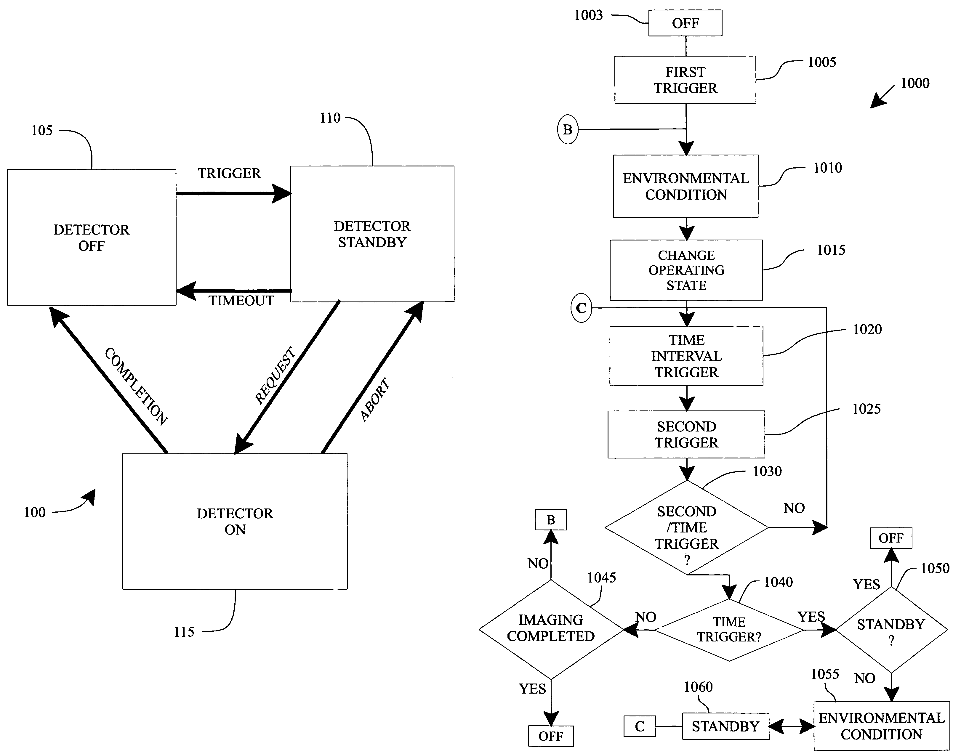
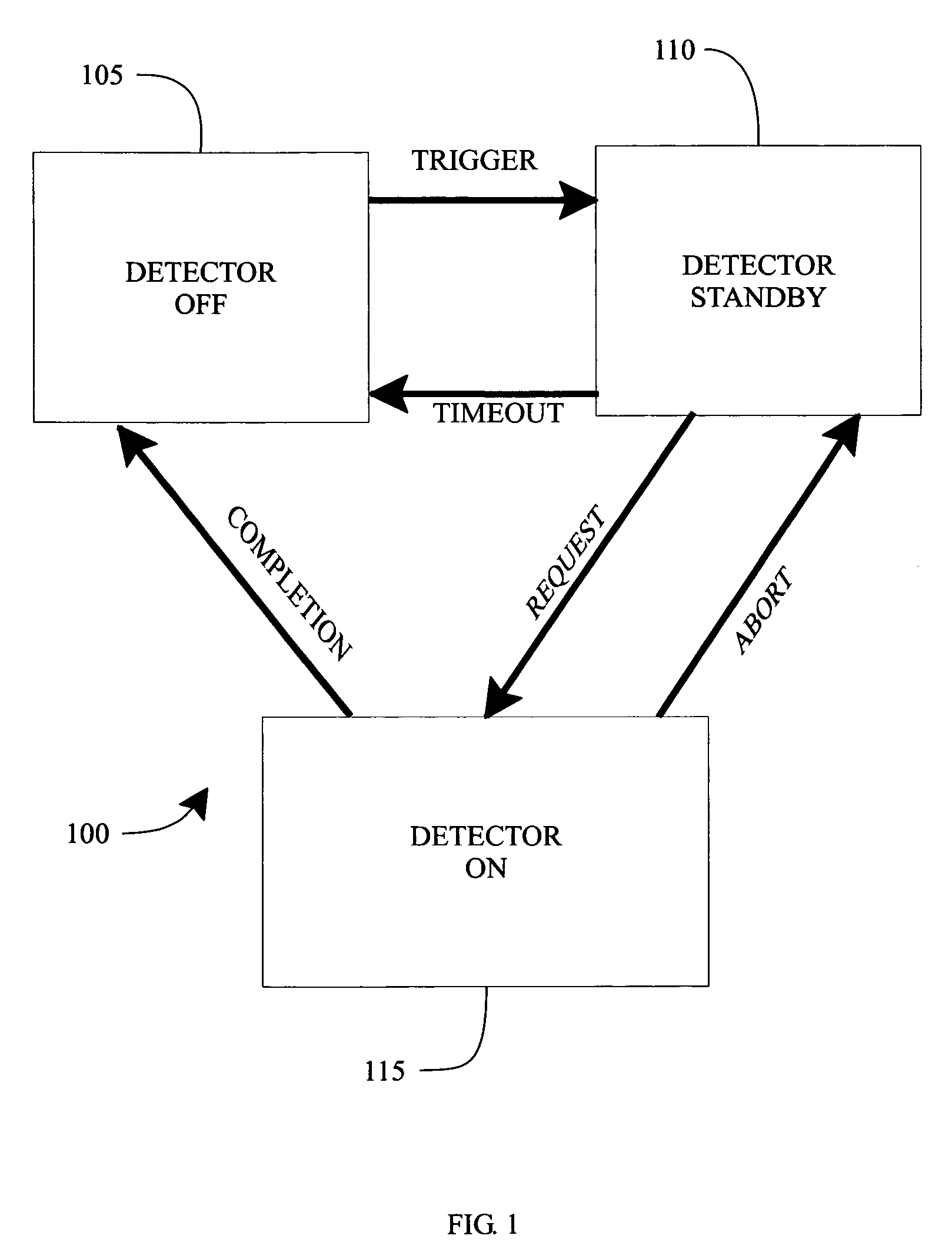
[0028]FIG. 1 is an overview of a representation of power consumption states 100 in a device such as an image detector, according to an embodiment. Operating states include an “OFF” state, a “Standby” state and an “ON” state. These states are selected to achieve maximum power conservation and optimal temperature management.

[0029]In OFF state 105, limited or no power is applied to the dev...


PUM


Abstract

Systems and methods are provided for managing power consumption of a medical imaging detector by the use of triggering signals, environmental condition data, and / or determination of a variable time interval triggering event that is unique for each power consumption state. Systems and methods are provided for managing power and temperature of a device, after receiving a request for a function to be performed by the device determining an “on” trigger component, an “off” trigger component, associated circuits for performing the received function, providing power to the associated circuits upon the occurrence of the “on” trigger component, and removing power to the associated circuits upon the occurrence of the “off” trigger component. Further, an instruction is described for determining and displaying a variable time interval that is indicative of a time to change from one state to a desired state.

Description

RELATED APPLICATION[0001]This application is related to copending U.S. application Ser. No. 10 / 805,753, filed Mar. 22, 2004 entitled “Digital Radiography Detector with Thermal and Power Management.”FIELD OF THE INVENTION[0002]This invention relates generally to portable health care imaging devices more particularly to managing power and temperature of radiographic imaging detectors.BACKGROUND OF THE INVENTION[0003]Many medical devices serve the portable healthcare and emergency response markets. Examples of these devices are heart-rate monitors, glucometers, electrocardiogram (ECG) monitors, ultrasound imaging devices, and diagnostic medical imaging devices such as digital radiographic detectors. Regardless of the application, these devices must be small in size, lightweight and battery powered to provide the user of the device with optimum mobility and ease of use. However, the requirements necessary to achieve portability result in severe constraints on space, weight and power dis...

Claims


Application Information

Patent Timeline
Patent Type & Authority Patents(United States)
IPC IPC(8): H05G1/58G01T1/00A61B6/00G01T1/29G01T7/00H04N5/32H05G1/54
CPCG01T1/2985
Inventor PETRICK, SCOTT W.LANGLER, DONALD FGRANFORS, PAUL R.KUMP, KEN S.HAEN, AARON A.ODOGBA, JIBRILERTEL, JASON R.NEUMANN, DAVID C.LAMBERTY, JOHN R.XUE, PINGVAFI, HABIB
Owner GENERAL ELECTRIC CO
Why Eureka
Try Eureka