Bit gage hardfacing

a hardfacing and gage technology, applied in the field of earth boring bits, can solve the problems of reducing the life of the bit,

Active Publication Date: 2007-07-10
BAKER HUGHES INC
View PDF7 Cites 35 Cited by
  • Summary
  • Abstract
  • Description
  • Claims
  • Application Information

AI Technical Summary

Benefits of technology

[0007]In this invention, the gage surface has a hardfacing of carbide particles in a metallic matrix. The hardfacing extends from the inner edge of the gage surface to the cutting elements of the heel row and to trimmer cutting elements. A plurality of channels on the gage surface allows for the displacement of material generated by the cutting elements and trimmers.

Problems solved by technology

Under very abrasive formation conditions, the gage surface will round over and wear away the hardfacing.
The gage surface will quickly wear, and the useful life of the bit will then be over because the bit will no longer be able to drill in-gage, causing bearing failure.

Method used


Image

  • Bit gage hardfacing
  • Bit gage hardfacing
  • Bit gage hardfacing

Examples


Embodiment Construction

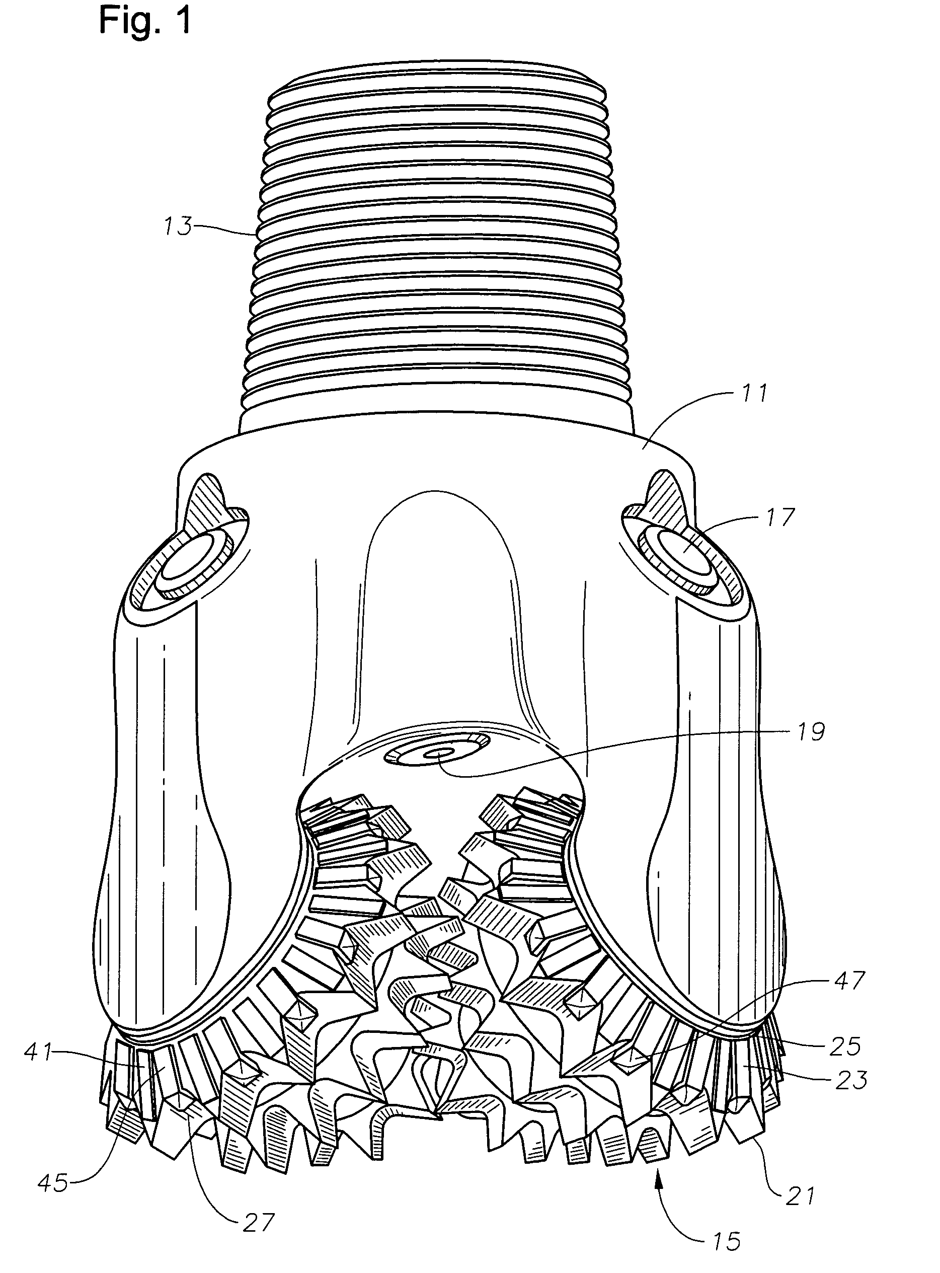
[0015]Referring to FIG. 1, the earth boring bit shown has a body 11 with a threaded upper end 13 for securing to a drill string. In this example, three cones 15 are rotatably mounted to depending bearing pins (not shown) of body 11. Body 11 has lubricant reservoirs for supplying lubricant to the bearings supporting each cone 15. A compensator 17 equalizes pressure differential between fluid in the borehole with the pressure of the lubricant. Body 11 has nozzles 19 for discharging drilling fluid, the drilling fluid sweeping cuttings from the borehole and returning them to the surface.

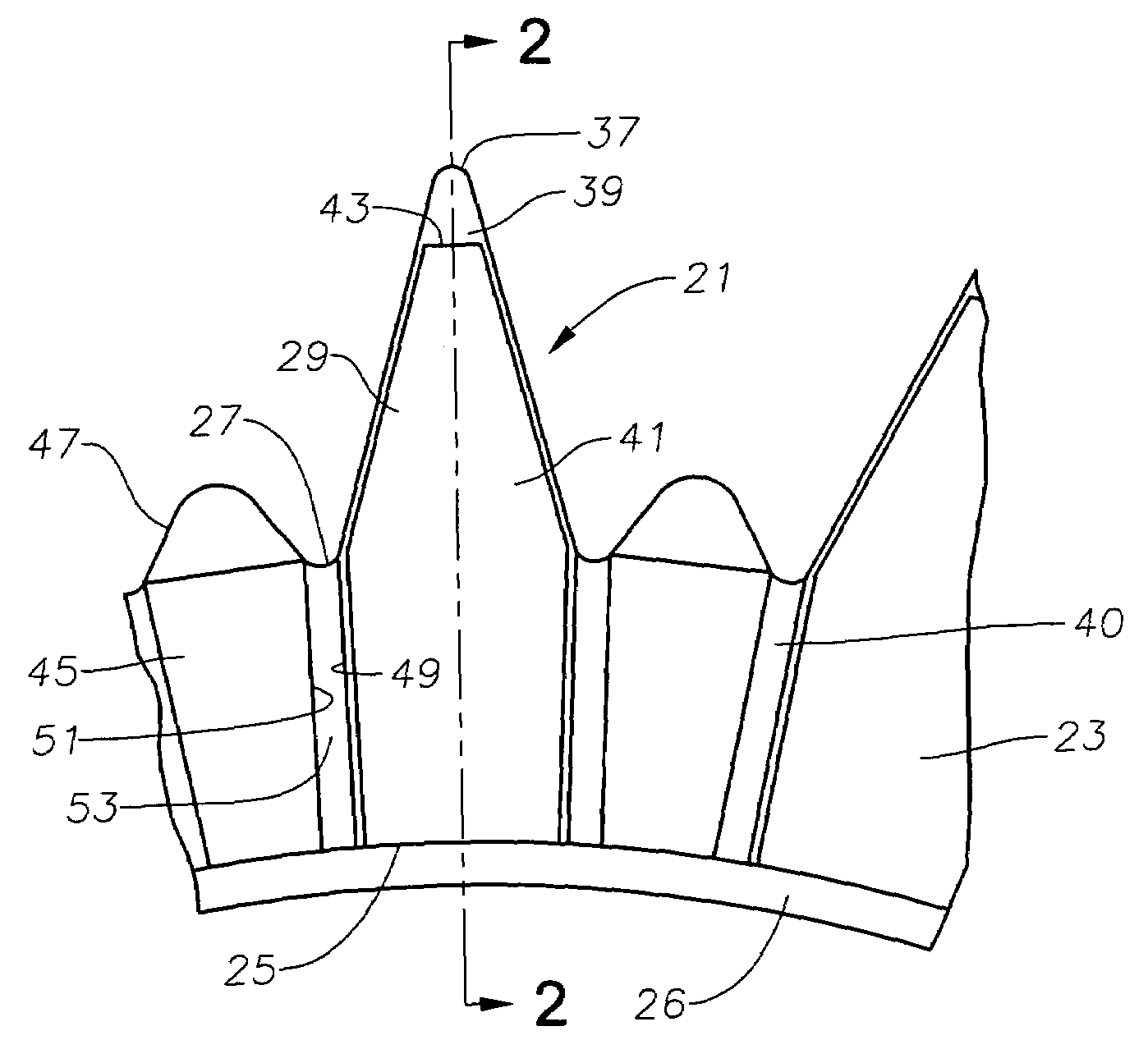
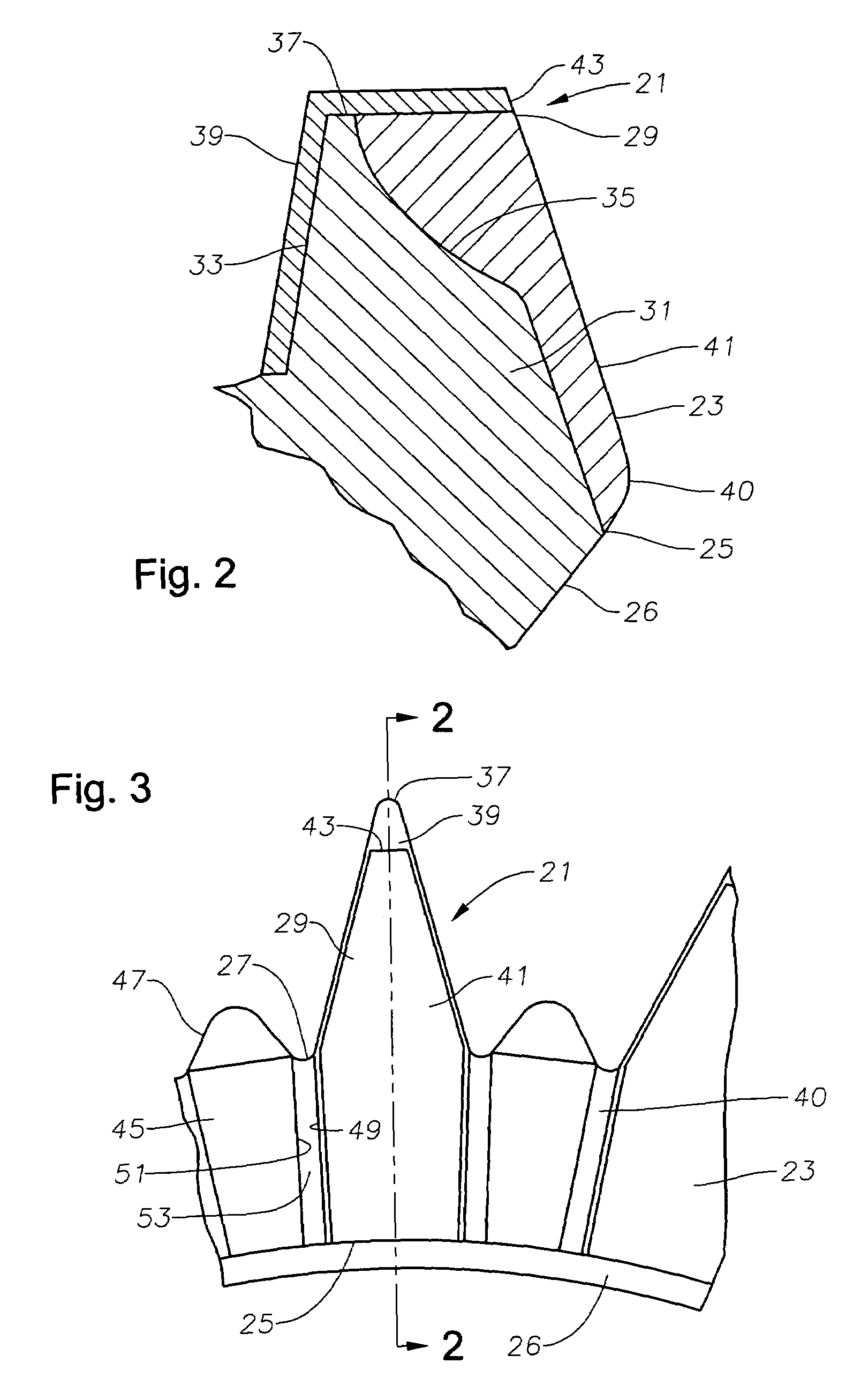
[0016]Each cone 15 has a generally frusto-conical main portion containing at least two rows of cutting elements, including a heel row 21. Heel row 21 is the row closest to a gage surface 23. Gage surface 23 engages the sidewall of the borehole as body 11 and each cone 15 rotates. Gage surface 23 thus determines the diameter of the borehole. In this embodiment, the cutting elements are milled teeth that a...


PUM


Abstract

An earth boring bit has at least one rotatable cone with a gage surface that engages a sidewall of a wellbore as the bit rotates. The gage surface has hardfacing bars spaced circumferentially apart from each other. A first group of the hardfacing bars extends from the inner edge of the gage surface to gage sides of the heel row cutting elements. A second group of the hardfacing bars extends from the inner edge of the gage surface to spaces between the heel row cutting elements, forming trimmer cutting elements. The hardfacing bars are made up of carbide particles in a metallic matrix.

Description

FIELD OF THE INVENTION[0001]This invention relates in general to earth boring bits, and in particular to bits having hardfacing on the bit gage surface to reduce wear.BACKGROUND OF THE INVENTION[0002]A common type of earth boring bit has rotatable cones. Each cone is rotatably mounted to a bearing pin that depends from the body of the bit. The cones have cutting elements that disintegrate the earth formation as the bit body is rotated. The cutting elements may comprise tungsten carbide compacts press-fitted into holes in the supporting metal of the cones. Alternately, the cutting elements may be milled teeth that are integrally formed from the cone metal.[0003]Each cone has a gage surface that engages the side of the bore hole as the bit rotates. In milled teeth cones, the teeth of the heel row, which is the row closest to the borehole wall, have gage sides that typically blend into the gage surface. The gage surface is an annular area that extends from a backface of the cone and jo...

Claims


Application Information

Patent Timeline
Patent Type & Authority Patents(United States)
IPC IPC(8): E21B10/00
CPCE21B17/1092
Inventor OVERSTREET, JAMES L.BUSKE, ROBERT J.PESSIER, RUDOLF C.MORGAN, JEREMY K.
Owner BAKER HUGHES INC
Why Eureka
Try Eureka