Dimmer having a power supply monitoring circuit

a monitoring circuit and dimmer technology, applied in the direction of electric variable regulation, process and machine control, instruments, etc., can solve the problems of small dimming range, inability to turn on the fets for the entire length of a half-cycle, and higher intensity of the load that is closer, so as to reduce the on-time and increase the on-time

Active Publication Date: 2007-07-10
LUTRON TECH CO LLC
View PDF27 Cites 189 Cited by
  • Summary
  • Abstract
  • Description
  • Claims
  • Application Information

AI Technical Summary

Benefits of technology

[0009]According to the present invention, a two-wire dimmer for control of a lighting load from a source of AC voltage includes a semiconductor switch, a power supply, and a control circuit. The semiconductor switch is operable to be coupled between the source of AC voltage and the lighting load and has a conducting state and a non-conducting state. The power supply has an input that receives an input voltage and is operable to draw current from the source of AC voltage during the non-conducting state of the semiconductor switch. The control circuit is operable to control the semiconductor switch into the conducting state for an on-time each half-cycle of the AC voltage and is coupled to the input of the power supply for monitoring the input voltage of the power supply. The control circuit is operable to decrease the on-time when the input voltage of the power supply falls below a first predetermined level. Further, the control circuit is operable to increase the on-time when the input voltage rises above a second predetermined level greater than the first level.

Problems solved by technology

So, the FETs cannot be turned on for the entire length of a half-cycle, even when the maximum voltage across the load is desired.
However, the worst-case condition is not normally encountered in practice, and under typical conditions, the FETs could normally be turned off for a shorter amount of time at the end of each half-cycle, thus conducting current to the load for a greater amount of time resulting in a higher intensity of the load that is closer to the intensity achieved when only a standard wall switch is connected in series with the load.
Prior art dimmers have held the minimum off-time constant under all conditions, and thus, have suffered from a small dimming range.

Method used


Image

  • Dimmer having a power supply monitoring circuit
  • Dimmer having a power supply monitoring circuit
  • Dimmer having a power supply monitoring circuit

Examples


Embodiment Construction

[0016]The foregoing summary, as well as the following detailed description of the preferred embodiments, is better understood when read in conjunction with the appended drawings. For the purposes of illustrating the invention, there is shown in the drawings an embodiment that is presently preferred, in which like numerals represent similar parts throughout the several views of the drawings, it being understood, however, that the invention is not limited to the specific methods and instrumentalities disclosed.

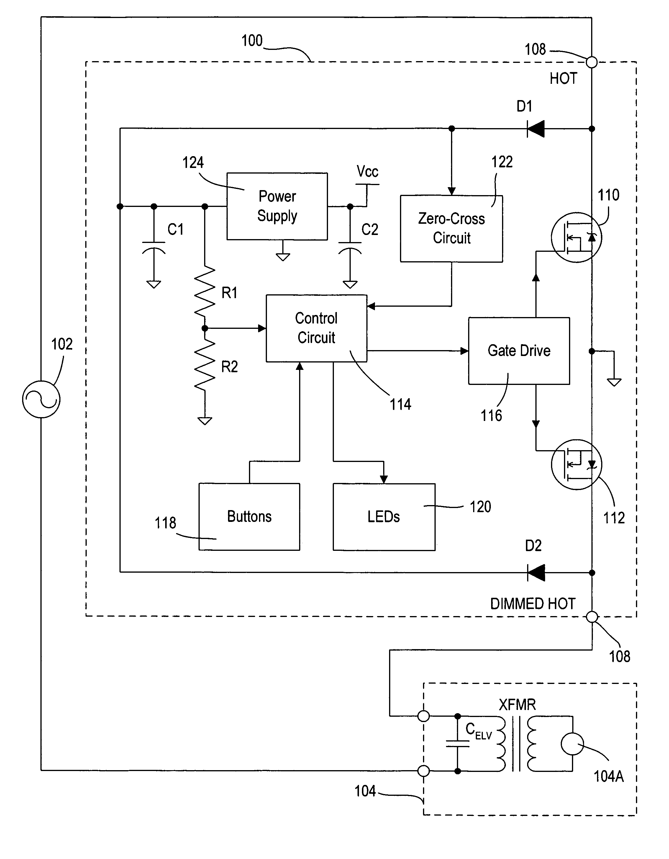
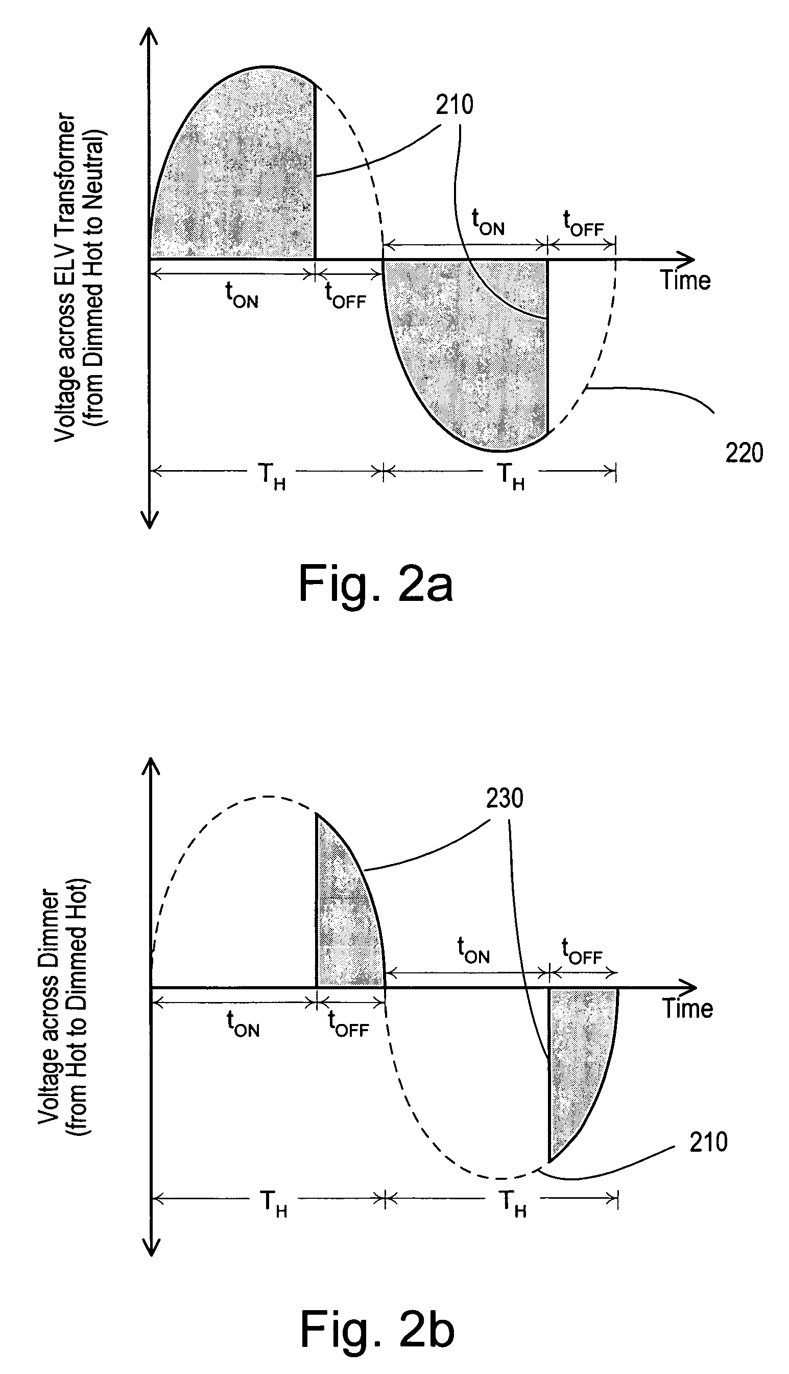
[0017]FIG. 1 shows the two-wire dimmer 100 of the present invention, which is connected in series between an AC power supply 102 and an ELV lighting load 104. The dimmer 100 has two connections: a HOT connection 106 to the AC power supply 102 and a DIMMED HOT connection 108 to the lighting load 104. Since ELV loads operate at a low-voltage level (such as 12 volts or 24 volts), a step-down transformer XFMR is required for the ELV lamp 104A. The ELV transformer XFMR is typically c...


PUM


Abstract

A two-wire dimmer for control of a lighting load from an alternating-current (AC) power source includes a semiconductor switch, a power supply, and a control circuit. The power supply includes an energy storage input capacitor that is able to charge only when the semiconductor switch is non-conductive. The control circuit continuously monitors the voltage on the input capacitor and automatically decreases the maximum allowable conduction time of the semiconductor switch when the voltage falls to a level that will not guarantee proper operation of the power supply. The dimmer of the present invention is able to provide the maximum possible conduction time of the semiconductor switch at high end (i.e., maximum light intensity) while simultaneously ensuring sufficient charging time for proper operation of the power supply, and hence, the dimmer.

Description

FIELD OF THE INVENTION[0001]The present invention relates to a two-wire load control device, specifically a two-wire dimmer for electronic low-voltage (ELV) lighting loads.BACKGROUND OF THE INVENTION[0002]Low-voltage lighting, such as electronic low-voltage (ELV) and magnetic low-voltage (MLV) lighting, is becoming very popular. Low-voltage lamps allow for excellent, precise sources of illumination, extended lamp life, higher efficiencies than incandescent lamps, and unique lighting fixtures, such as track lighting. To power an electronic low-voltage lamp, an ELV transformer is required to reduce a line voltage (typically 120 VAC or 240 VAC) to a low-voltage level (such as 12 volts or 24 volts) to power the ELV lamp.[0003]Many prior art two-wire dimmers exist for control of ELV lighting loads. A conventional two-wire dimmer has two connections: a “hot” connection to an alternating-current (AC) power supply and a “dimmed hot” connection to the lighting load. Standard dimmers use one ...

Claims


Application Information

Patent Timeline
Patent Type & Authority Patents(United States)
IPC IPC(8): H05B37/02H05B41/16
CPCH05B39/048Y02B20/148Y02B20/00
Inventor DEJONGE, STUARTKUMAR, RUSSIKESH
Owner LUTRON TECH CO LLC
Why Eureka
Try Eureka