Organic electronic lighting system

a lighting system and electronic technology, applied in the field of electronic lighting systems of organic materials, can solve the problems of short life times of copper anode electrode tracks, unsuitable for large-scale production, etc., and achieve the effect of increasing the lifetime of the operation of the lighting system

Inactive Publication Date: 2017-05-25
CAMBRIDGE DISPLAY TECH LTD
View PDF1 Cites 0 Cited by
  • Summary
  • Abstract
  • Description
  • Claims
  • Application Information

AI Technical Summary

Benefits of technology

[0004]According to the present invention there is therefore provided an ITO-free organic lighting system, the system comprising: a substrate bearing a set of anode electrode metal tracks; a conductive organic layer over said metal tracks; an organic light emitting layer over said conductive organic layer; and a cathode electrode layer over said organic light emitting layer; and a driver system having an output electronically coupled to said anode electrode metal tracks and to said cathode electrode layer, to drive said organic light emitting layer with a drive current to emit light; wherein said drive current is pulsed such that an operational lifetime of said lighting system is increased.
[0005]Experimentally this approach has been demonstrated to mitigate device failure, in particular where a copper anode electrode grid is employed—which facilitates good performance at low cost. Without wishing to be bound by theory it is speculated that this may be related to a reduction in migration of copper ions into the conductive organic layer.
[0006]In embodiments a percentage on-time of the light emitting layer is reduced from 100%, and a peak value of the drive current is increased, such that for a given, for example maximum, light output, the light output is maintained whilst driving the organic light emitting device with a reduced on-time.
[0008]Although the copper may be in the form of a copper alloy to mitigate electromigration, surprisingly embodiments of the invention work well with low cost “pure” copper, that is copper which is not a deliberate alloy but which nonetheless may contain impurities up to, for example, 0.1% 0.5%, 1%, 2%, 3% or even 5%.
[0009]Nonetheless, in embodiments of this aspect of the invention, and also in embodiments of the other aspects of the invention described below, the anode electrode metal comprises a NiP alloy (a mixture of nickel and phosphorus), in particular a copper NiP alloy. Then, preferably, the NiP alloy forms a protective or a capping layer on the anode electrode metal, for example copper. This may be deposited by electro- or electrolessly plating the NiP alloy on the metal, for example copper. It has been found that this helps to increase device lifetime.
[0014]In a related aspect the invention provides a method of increasing the lifetime of an organic lighting system, in particular an ITO-free organic lighting system, the method comprising: providing an organic lighting element comprising: a substrate bearing a set of anode electrode metal tracks; a conductive organic layer over said metal tracks; an organic light emitting layer over said conductive organic layer; and a cathode electrode layer over said organic light emitting layer; wherein said metal comprises copper, and wherein said conductive organic layer comprises a doped conducting polymer; and driving said organic lighting element with a pulsed current drive.

Problems solved by technology

Use of such material provides relatively good lateral conductivity and performance but is expensive and, in the long term, is not desirable for large scale production.
However in practice devices with copper anode electrode tracks are observed to have only short life times, typically a few hours.

Method used


Image

  • Organic electronic lighting system
  • Organic electronic lighting system
  • Organic electronic lighting system

Examples


Embodiment Construction

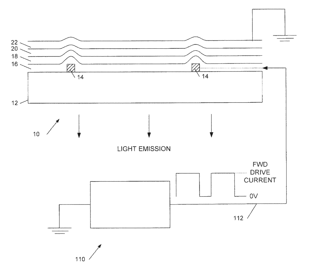
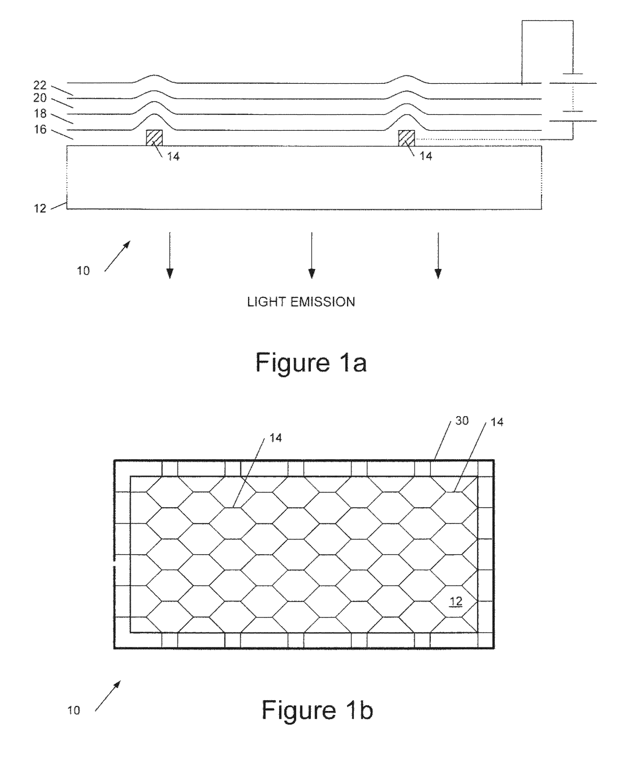
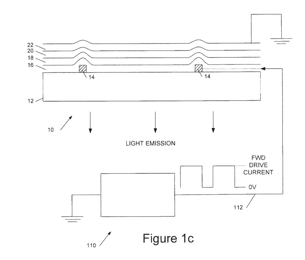
Organic Light Emitting Structures

[0025]In this specification references to organic LEDs include organometallic LEDs, and OLEDs fabricated using either polymers or small molecules. Examples of polymer—based OLEDs are described in WO 90 / 13148, WO 95 / 06400 and WO 99 / 48160; examples of so called small molecule based devices are described in U.S. Pat. No. 4,539,507.

[0026]OLED devices (which here includes organometallic devices and devices including one or more phosphors) may be fabricated using either polymers or small molecules in a range of colours and in multi-coloured displays depending upon the materials used. For general background information reference may be made, for example, to WO90 / 13148, WO95 / 06400, WO99 / 48160 and U.S. Pat. No. 4,539,570, as well as to “Organic Light Emitting Materials and Devices” edited by Zhigang Li and Hong Meng, CRC Press (2007), ISBN 10: 1-57444-574X, which describes a number of materials and devices, both small molecule and polymer.

[0027]To aid in unde...


PUM


Abstract

A method of increasing the lifetime of an ITO-free organic lighting system comprises: providing an organic lighting element having a substrate (12) bearing a set of anode electrode metal tracks (14), a conductive organic layer (16) over said metal tracks, an organic light emitting layer (18) over said conductive organic layer, and a cathode electrode layer (20) over said organic light emitting layer, wherein said metal comprises copper, and wherein said conductive organic layer comprises a doped conducting polymer, and driving the organic lighting element with a pulsed current drive. A biphasic pulse is employed having a first, on-phase with a defined current drive and a second, off-phase with a drive having a defined potential difference of zero volts across the lighting element. The anode electrode metal may have a higher work function than the cathode electrode layer. During said zero level drive portion the different work functions provide a reverse bias electric field within the organic lighting element.

Description

FIELD OF THE INVENTION[0001]This invention relates to organic electronic lighting systems such as OLED (organic light emitting diode) lighting systems and, in particular, to techniques for reducing the cost and increasing the lifetime of such systems.BACKGROUND TO THE INVENTION[0002]Reducing the cost and increasing the lifetime of organic light emitting devices is important to the success of this technology. Typically such devices incorporate one transparent electrode, generally ITO (indium tin oxide) to enable the light to escape from the structure. Use of such material provides relatively good lateral conductivity and performance but is expensive and, in the long term, is not desirable for large scale production. The degradation of ITO-based devices has been investigated in “White-Light Generation and OLED Lifetime Issues”, by Aaron R. Johnson, Thesis, 2008; and in “Effect of driving method on the degradation of organic light emitting diodes”, P. Cusumano, F. Buttitta, A. Di Crist...

Claims


Application Information

Patent Timeline
Patent Type & Authority Applications(United States)
IPC IPC(8): H05B33/08H01L51/52H01L27/32H01L51/50H05B44/00
CPCH05B33/0896H01L51/5088H01L2251/562H01L27/3213H01L51/5206H05B45/60Y02B20/30H10K50/814H10K71/841H05B33/26H10K50/81H10K50/813H10K50/17H10K59/12H10K71/831
Inventor CONWAY, NATASHA M.J.BAKER, COLINBENZIE, PHILIPDOUST, ALEXANDERMACCARTHY, NIALL
Owner CAMBRIDGE DISPLAY TECH LTD
Why Eureka
Try Eureka