Multiple lamp balance transformer and drive circuit

a technology of multi-lamp balance transformer and drive circuit, which is applied in the direction of lighting apparatus, electrical equipment, light sources, etc., can solve the problems of increasing the size of the lcd panel, difficulty in maintaining consistent impedance for all lamps, and single lamps no longer satisfying illumination requirements, etc., to enhance product competitiveness, reduce manpower and assembly time, and improve product competitiveness

Inactive Publication Date: 2007-07-10
LIEN CHANG ELECTRONICS ENTERPRISE
View PDF4 Cites 17 Cited by
  • Summary
  • Abstract
  • Description
  • Claims
  • Application Information

AI Technical Summary

Benefits of technology

[0010]The drive circuit of the multiple lamp balance transformer in accordance with the present invention adopts the foregoing multiple lamp balance transformer connected to a plurality of lamps while using a controller that supplies currents to the lamps through a boost transformer. A current detect / protect circuit connected to the two first coils, the two second coils and the controller are used to detect the current passing through the two first coils and the two second coils. The current detect / protect circuit converts the operating current of the lamps into a voltage to be sent to the controller, so that the controller controls and supplies sufficient power for the lamps.
[0011]The drive circuit of the invention adopts a multiple lamp balance transformer to balance the plurality of lamps, so that the size of the drive circuit is smaller than that of the prior art. At the same time, the cost of the invention can be lowered, and the manpower and working hours for assembly can be reduced to enhance product competitiveness.

Problems solved by technology

Due to technological advancements and consumer requirements, the size of an LCD panel becomes increasingly larger and a single lamp no longer satisfies the illumination requirements thereof.
Since the height of the CCFL varies and the CCFL has negative impedance, it is difficult to maintain consistent impedance for all lamps.
As a result, the impedance of each lamp varies and the current cannot be equalized.
If the currents between the lamps are not equal, the brightness will be uneven.
An excessively large current will shorten the life of the lamps, and will result in a different aging rate of each lamp.
Such arrangement not only increases the size of the whole drive circuit, but also increases the cost thereof, and wastes manpower and working hours for assembly.

Method used


Image

  • Multiple lamp balance transformer and drive circuit
  • Multiple lamp balance transformer and drive circuit
  • Multiple lamp balance transformer and drive circuit

Examples


Embodiment Construction

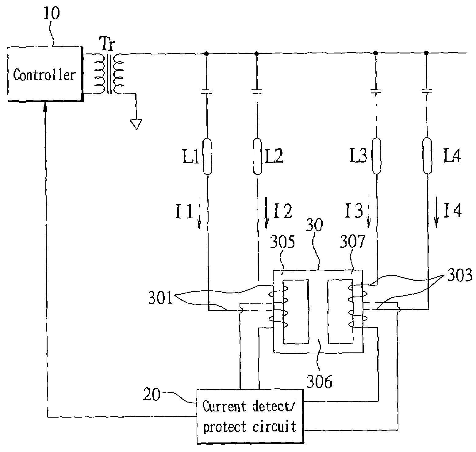
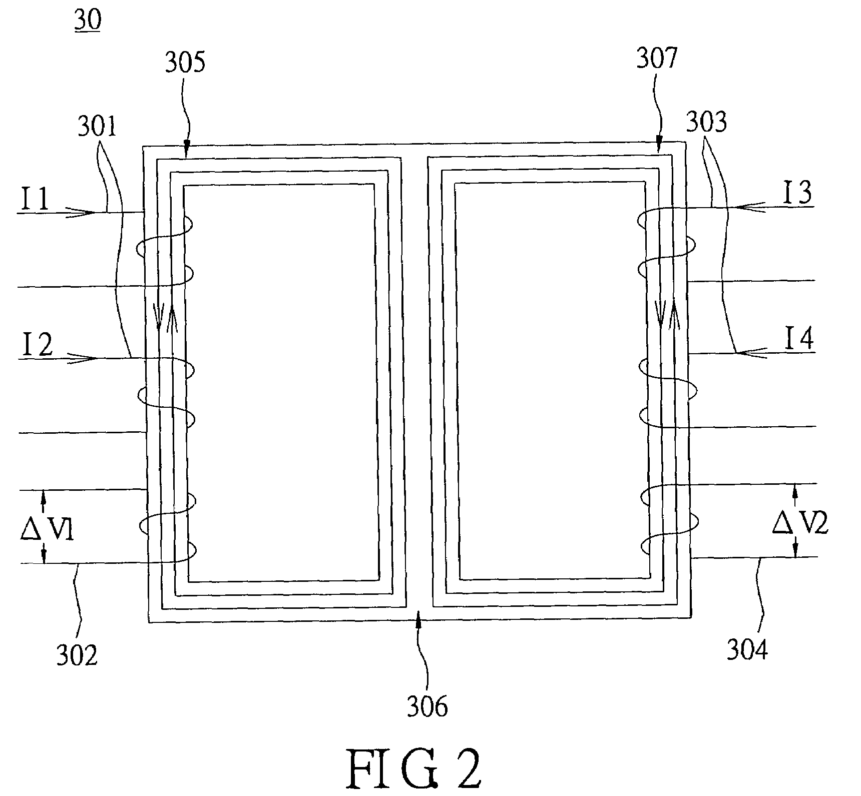
[0019]Reference is made to FIG. 2 for the schematic circuit diagram of a multiple lamp balance transformer of the present invention. In FIG. 2, a multiple lamp balance transformer 30 comprises a magnetic core having a first side post 305, a second side post 307, and a middle post 306 disposed between the first side post 305 and the second side post 307. The middle post 306 is used to divide the first side post 305 and the second side post 307 into two, separate, closed magnetic flux paths. Two first coils 301 are wound around the first side post 305 in opposite directions; two second coils 303 are wound around the second side post 307 in opposite directions. The number of windings of the two first coils 301 is equal to that of the two second coils 303, and the impedance property of the coils and Lenz's Law are used to balance the operating currents I1, I2, I3, I4 passing through the lamps and the coils.

[0020]In the multiple lamp balance transformer 30 of the present invention, the t...


PUM


Abstract

The invention describes a multiple lamp balance transformer and a drive circuit. The multiple lamp balance transformer has two magnetic cores with a closed magnetic flux path and two coils wound around the closed magnetic flux path. The two coils have the same number of windings. The impedance property of the coil and Lenz's Law are used to balance the operating current of the lamps connected to the coils. The drive circuit has a multiple lamp balance transformer connected to several lamps, and a boost transformer uses a controller to supply the current and voltage to the lamps. A current detect / protect circuit connected to the coils and the controller detects the current passing through the coils and converts the operating current of the lamp into a voltage to be sent to the controller, so that the controller controls and provides sufficient power to the lamps.

Description

BACKGROUND OF THE INVENTION[0001]1. Field of the Invention[0002]The present invention relates to a multiple lamp balance transformer and a drive circuit, and more particularly to a transformer and a drive circuit used in a lamp equalizing circuit of a cold cathode fluorescent lamp (CCFL).[0003]2. Description of Related Art[0004]A cold cathode fluorescent lamp (CCFL) is generally used as a light source of a backlight module for liquid crystal display (LCD) panels. The CCFL is driven by a drive circuit of an inverter. Due to technological advancements and consumer requirements, the size of an LCD panel becomes increasingly larger and a single lamp no longer satisfies the illumination requirements thereof. Therefore, two or more lamps are needed. To assure an even brightness for the LCD panels, it is necessary to adjust the current of each lamp constantly, so that the current passing through each lamp is equal. Since the height of the CCFL varies and the CCFL has negative impedance, it...

Claims


Application Information

Patent Timeline
Patent Type & Authority Patents(United States)
IPC IPC(8): H05B41/26
CPCH05B41/2822
Inventor CHAN, CHUN-KONGWANG, JENG-SHONG
Owner LIEN CHANG ELECTRONICS ENTERPRISE
Why Eureka
Try Eureka