
Peaking transmission line receiver for logic signals

a transmission line receiver and logic signal technology, applied in logic circuit coupling/interface arrangement, pulse technique, instruments, etc., can solve the problem of not providing an easy way to vary the compensation amount, and achieve the effect of preventing accentuating high frequency noise components, low frequency gain, and low frequency gain

Inactive Publication Date: 2007-07-10
IBM CORP
View PDF7 Cites 5 Cited by
  • Summary
  • Abstract
  • Description
  • Claims
  • Application Information

AI Technical Summary

Benefits of technology

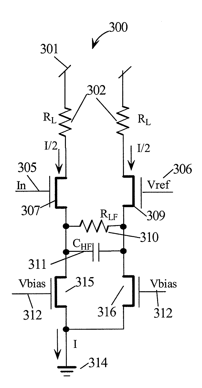
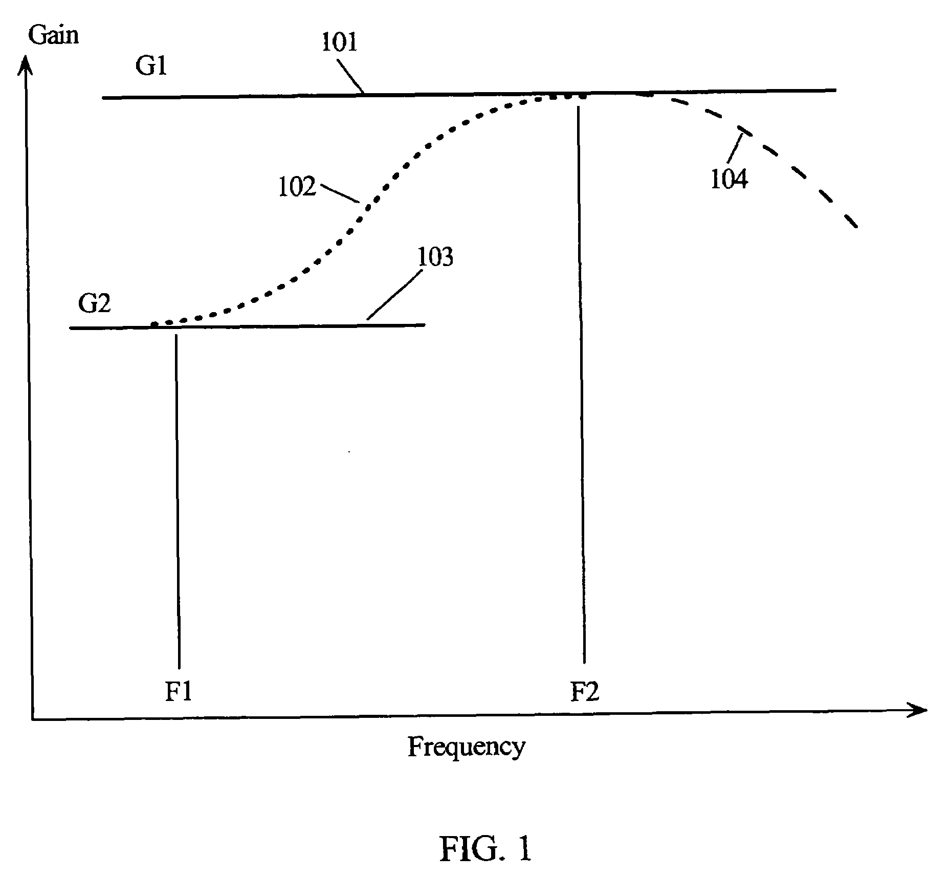
[0012]Embodiments of the present invention partition the frequency compensated differential stage of a pseudo differential receiver into two halves with each half being biased with separate current sources I / 2. The two current sources are then coupled back together with a network comprising a parallel connection of a resistor and a capacitor. At low frequencies the capacitor is a high impedance relative to the resistor and thus the resistor coupling between the two half stages reduces the low frequency gain to less than the gain of directly coupled half stages. Likewise, the capacitor coupling between the two half stages makes the high frequency gain substantially the same as the gain of directly coupled half stages. In this manner, the receiver stage is frequency compensated by reducing the low frequency gain relative to the high frequency gain. This method prevents accentuating high frequency noise components and rather deemphasizes low frequency components that distorts logic state transitions at the receiver side. This embodiment provides frequency compensation but does not provide an easy way to vary the amount of compensation in a particular data input that does not suffer from significant losses.
[0013]In another embodiment of the present invention, two differential stages are operated in parallel sharing common load resistors. The first stage is uncompensated with a current source bias that is variable. The second stage is frequency compensated by reducing it low frequency gain. The second stage is also biased with a current source bias that is variable. In this embodiment the sum of the current source currents in each stage, while variable is held constant. If the current in one stage is increased the current in the other stage is reduced by the same amount. Since the two stages share a load resistor, this keeps the operating point the same. However, since each stage is operated a different current level, the dynamic impedance of each stage is different and thus their gains are different. If the current source in the frequency compensated stage is turned fully OFF and the current source in the uncompensated stage is turned fully ON, then the gain will be nominal and uncompensated. Likewise, by turning the frequency compensated stage fully ON and the current source in the uncompensated stage is turned fully OFF, then the gain will be nominal and compensated. Current values in between these extremes will afford varying degrees of compensation.

Problems solved by technology

This embodiment provides frequency compensation but does not provide an easy way to vary the amount of compensation in a particular data input that does not suffer from significant losses.

Method used


Image

  • Peaking transmission line receiver for logic signals
  • Peaking transmission line receiver for logic signals
  • Peaking transmission line receiver for logic signals

Examples


Embodiment Construction

[0026]In the following description, numerous specific details are set forth to provide a thorough understanding of the present invention. However, it will be obvious to those skilled in the art that the present invention may be practiced without such specific details. In other instances, well-known circuits may be shown in block diagram form in order not to obscure the present invention in unnecessary detail. For the most part, details concerning timing considerations and the like have been omitted inasmuch as such details are not necessary to obtain a complete understanding of the present invention and are within the skills of persons of ordinary skill in the relevant art.

[0027]Refer now to the drawings wherein depicted elements are not necessarily shown to scale and wherein like or similar elements are designated by the same reference numeral through the several views.

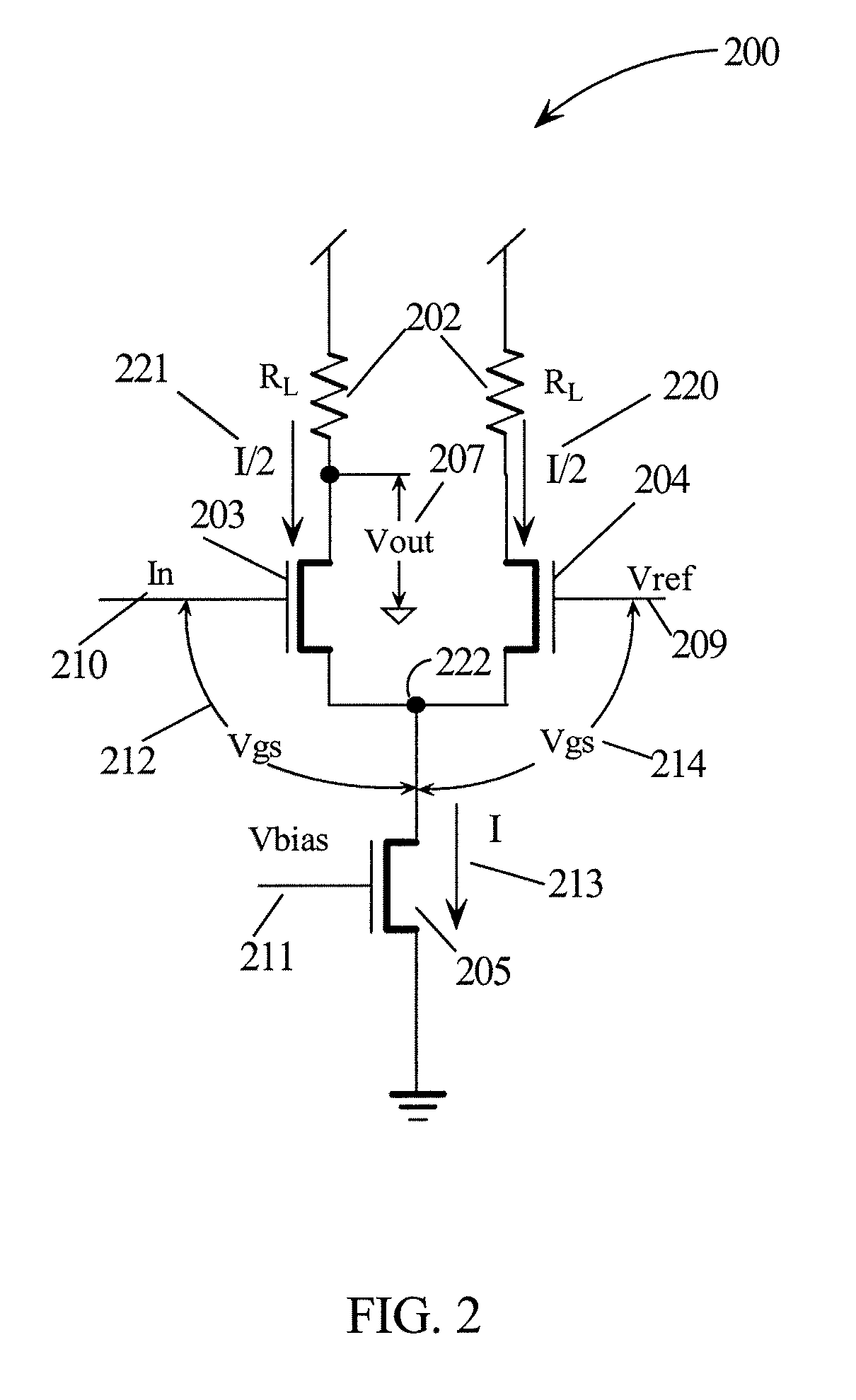
[0028]FIG. 6 is a circuit diagram of typical pseudo-differential signaling for transmitting data from a driver to ...


PUM


Abstract

A receiver circuit is configured as a frequency compensated differential amplifier having one input coupled to the output of a transmission line to receive a transmitted signal and the second input coupled to a reference voltage. The differential amplifier has a high frequency gain equivalent to the gain of an uncompensated differential stage for the transmitted signal. The compensated differential amplifier has an attenuated low frequency gain for signal frequencies substantially lower than the high frequency and a transitional gain for frequencies between the low and high frequencies. A compensated stage provides the portion of the signal with a compensated response and an uncompensated stage provides the portion of the amplified signal that is uncompensated. Bias control signals determine how much of the output signal is from the compensated and uncompensated stages as a means for customizing response from transmission lines with varying losses.

Description

TECHNICAL FIELD[0001]The present invention relates in general to board level transmission line drivers and receivers, and in particular, to receiver circuits for shaping receiver transmission line signals.BACKGROUND INFORMATION[0002]Digital computer systems have a history of continually increasing the speed of the processors used in the system. As computer systems have migrated towards multiprocessor systems, sharing information between processors and memory systems has also generated a requirement for increased speed for the off-chip communication networks. Designers usually have more control over on-chip communication paths than for off-chip communication paths. Off-chip communication paths are longer, have higher noise, impedance mismatches, and have more discontinuities than on-chip communication paths. Since off-chip communication paths are of lower impedance, they require more current and thus more power to drive.[0003]When using inter-chip high-speed signaling, noise and coup...

Claims


Application Information

Patent Timeline
Patent Type & Authority Patents(United States)
IPC IPC(8): H03F3/45H03K19/094
CPCG11C7/02G11C7/1078G11C7/1084
Inventor DREPS, DANIEL M.TRUONG, BAO G.WIEDEMEIER, GLEN A.
Owner IBM CORP
Learn More