BUCK converter circuit
A converter and circuit technology, applied in the field of buck converter circuits, can solve the problems affecting the stability of the power supply system, and achieve the effects of sufficient phase margin and gain margin, low and high frequency gain, and high voltage regulation accuracy.
- Summary
- Abstract
- Description
- Claims
- Application Information
AI Technical Summary
Problems solved by technology
Method used
Image
Examples
Embodiment Construction
[0019] It should be understood that the specific embodiments described here are only used to explain the present invention, not to limit the present invention.
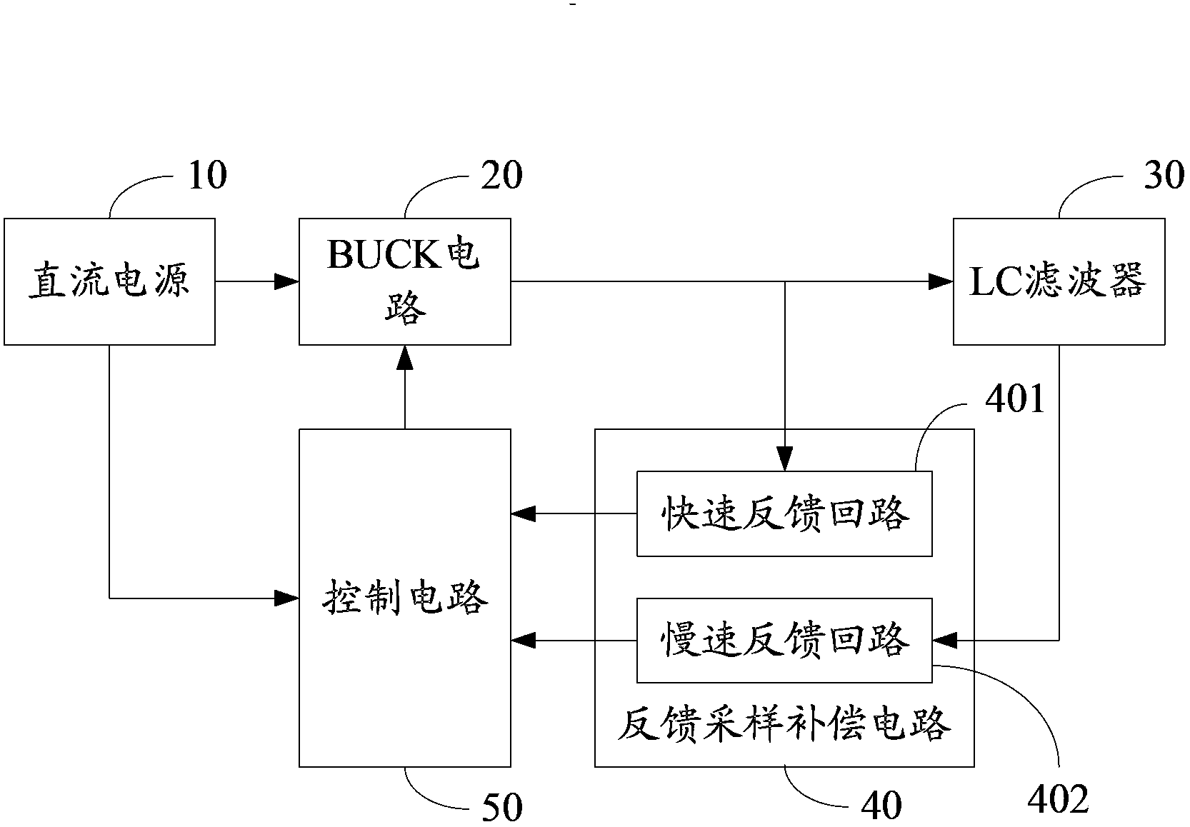
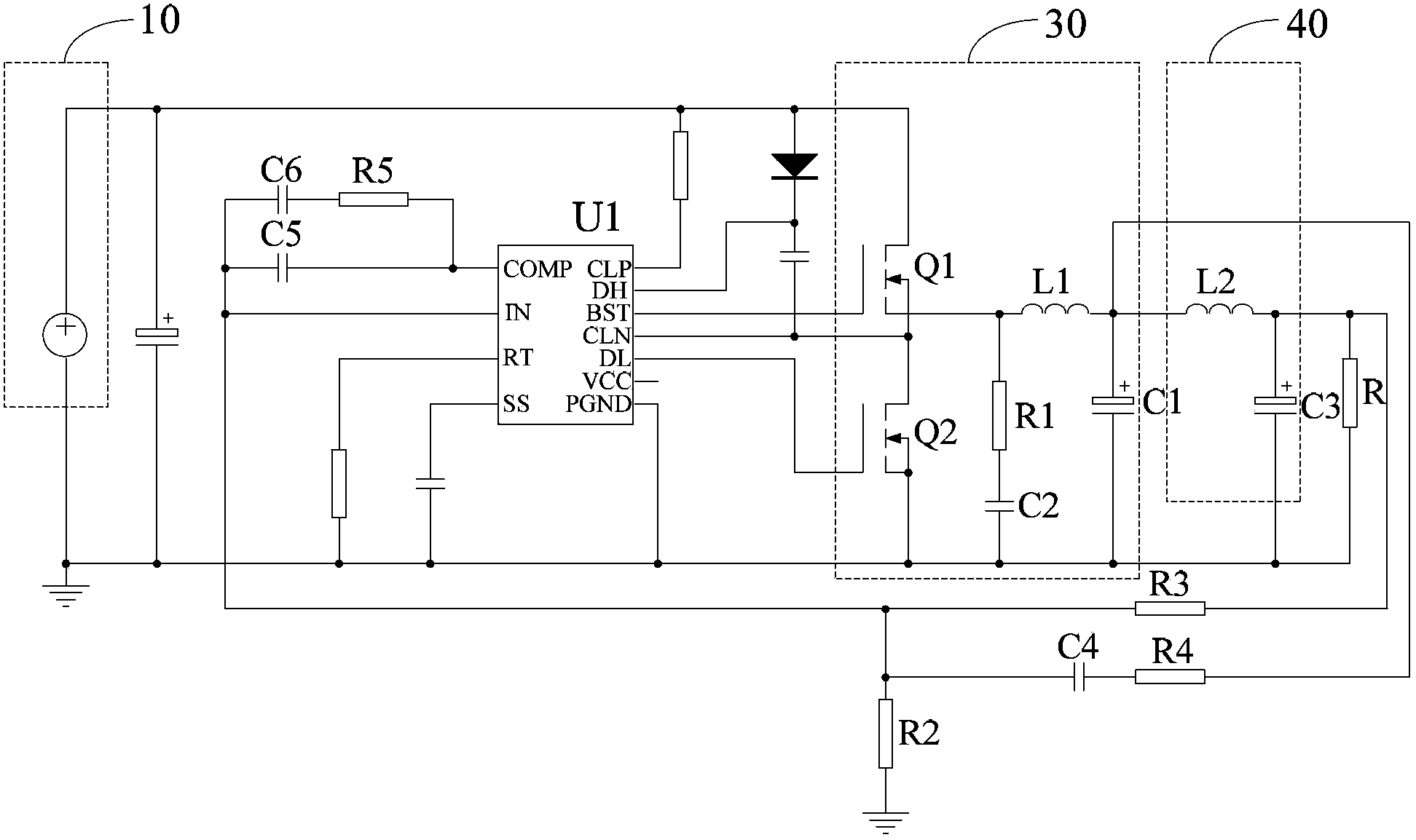
[0020] combined reference figure 1 and figure 2 , figure 1 It is a schematic structural diagram of a preferred embodiment of the BUCK converter circuit of the present invention, figure 2 It is a circuit diagram of a preferred embodiment of the BUCK converter circuit of the present invention. The BUCK converter circuit provided in this embodiment includes:
[0021] DC power supply 10, used to provide power supply voltage;
[0022] BUCK circuit 20, used to reduce the voltage of DC power supply 10;
[0023] The LC filter 30 is used to filter the voltage stepped down by the BUCK circuit 20 and output it to the load R;
[0024] The feedback sampling compensation circuit 40 is used for sampling and feedback compensation to the output voltage of the BUCK circuit 20 and the output voltage of the LC filter 30;
[0025...
PUM
 Abstract
Description
Claims
Application Information
 - R&D
- Intellectual Property
- Life Sciences
- Materials
- Tech Scout
- Unparalleled Data Quality
- Higher Quality Content
- 60% Fewer Hallucinations
Browse by: Latest US Patents, China's latest patents, Technical Efficacy Thesaurus, Application Domain, Technology Topic, Popular Technical Reports.
© 2025 PatSnap. All rights reserved.Legal|Privacy policy|Modern Slavery Act Transparency Statement|Sitemap|About US| Contact US: help@patsnap.com


