
Image forming apparatus and management system

a technology of image forming apparatus and management system, which is applied in the direction of electrographic process apparatus, instruments, optics, etc., can solve the problems of poor image quality of the resultant image, low density area roughening, and gradual lowering of the charging performance of the developer, and achieves high-quality image formation

Inactive Publication Date: 2007-07-10
CANON KK
View PDF9 Cites 6 Cited by
  • Summary
  • Abstract
  • Description
  • Claims
  • Application Information

AI Technical Summary

Benefits of technology

The present invention provides an image forming apparatus that can automatically replace the developer containing toner and carrier when the old developer becomes deteriorated. This helps to stabilize the carrier ratio in the developer and ensures high quality image formation. The image forming apparatus can selectively mount one of multiple developer supply containers containing developers with different carrier ratios, and the notification means can provide information on which developer supply container to select based on the deterioration of the carrier. The management system includes a communication management device, an information management device, and a notification device for managing the image forming apparatus.

Problems solved by technology

Accordingly, the carrier stirred together with the toner in the developing apparatus is liable to be deteriorated with an increasing frequency of stirring due to adhesion of the toner onto the surface of the carrier, so that a charging performance of developer is gradually lowered.
As a result, an image quality of the resultant image becomes poor.
For example, there have arisen such problems that roughening of image in a low density area becomes poor and fog on a white background and deterioration such as a trace of contamination of a charger due to toner scattering are caused to occur.
As a result, the resultant display apparatus has a complicated mechanism, thus being required to ensure a sufficient space therefor.

Method used


Image

  • Image forming apparatus and management system
  • Image forming apparatus and management system
  • Image forming apparatus and management system

Examples


embodiment 1

[0037]First of all, with reference to FIG. 11, a general structure of the image forming apparatus of the present invention and an image forming operation performed by the image forming apparatus will be described. As the image forming apparatus in this embodiment, an electrophotographic copying machine 1 is used.

[0038]More specifically, the image forming apparatus of this embodiment is an electrophotographic image forming apparatus, i.e., one having a drum-like electrophotographic photosensitive member (photosensitive drum) 2 as an image bearing member. As the image bearing member, it is also possible to use a belt-like electrophotographic photosensitive member.

[0039]In the image forming apparatus, an original on which a desired image is recorded is fed to an optical reading system 9 as an image reading portion by an original treating apparatus 11, and image information recorded on the original is read by a CCD 9a provided to the optical reading system 9 and then is sent to an image...

embodiment 2

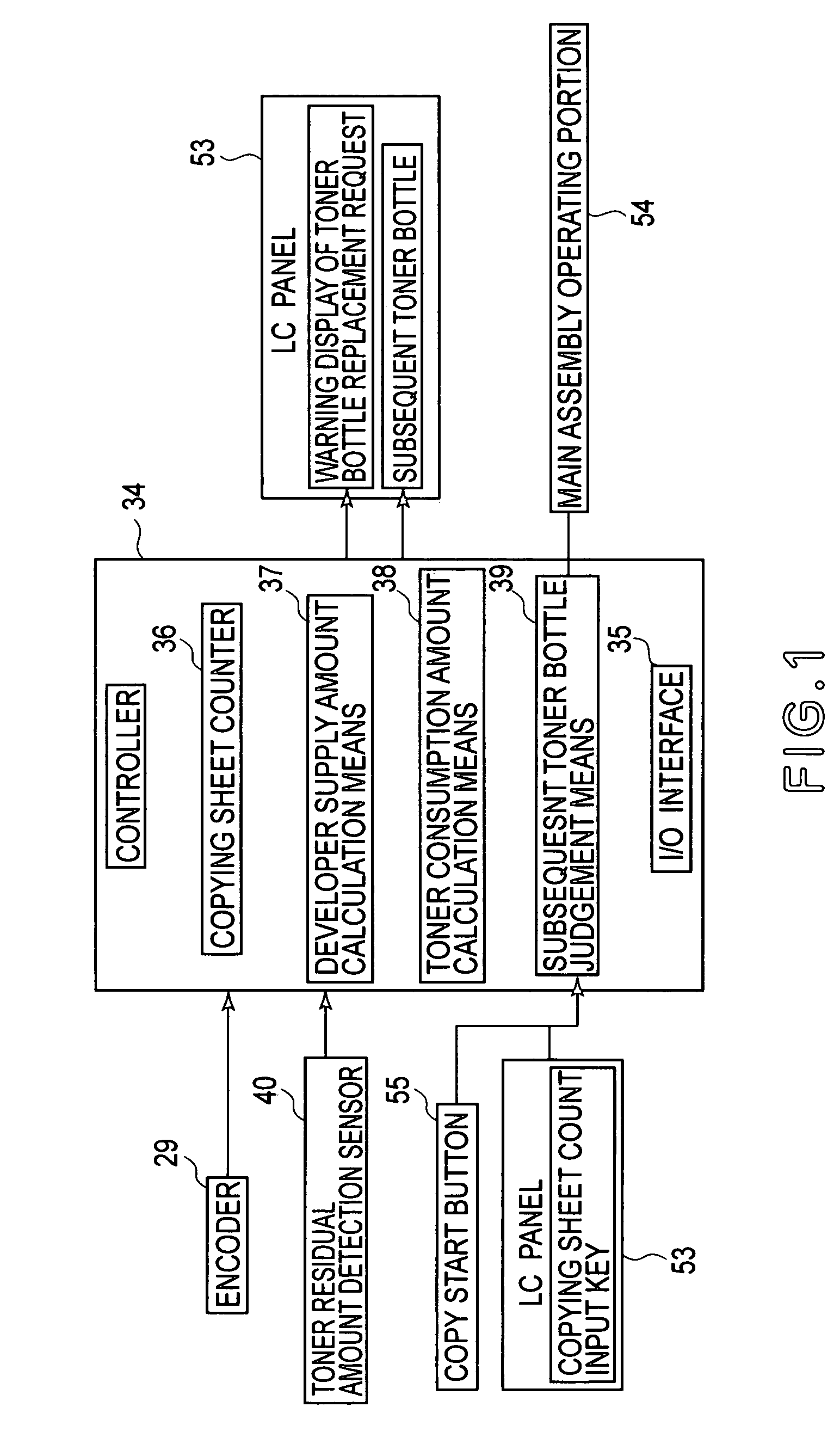
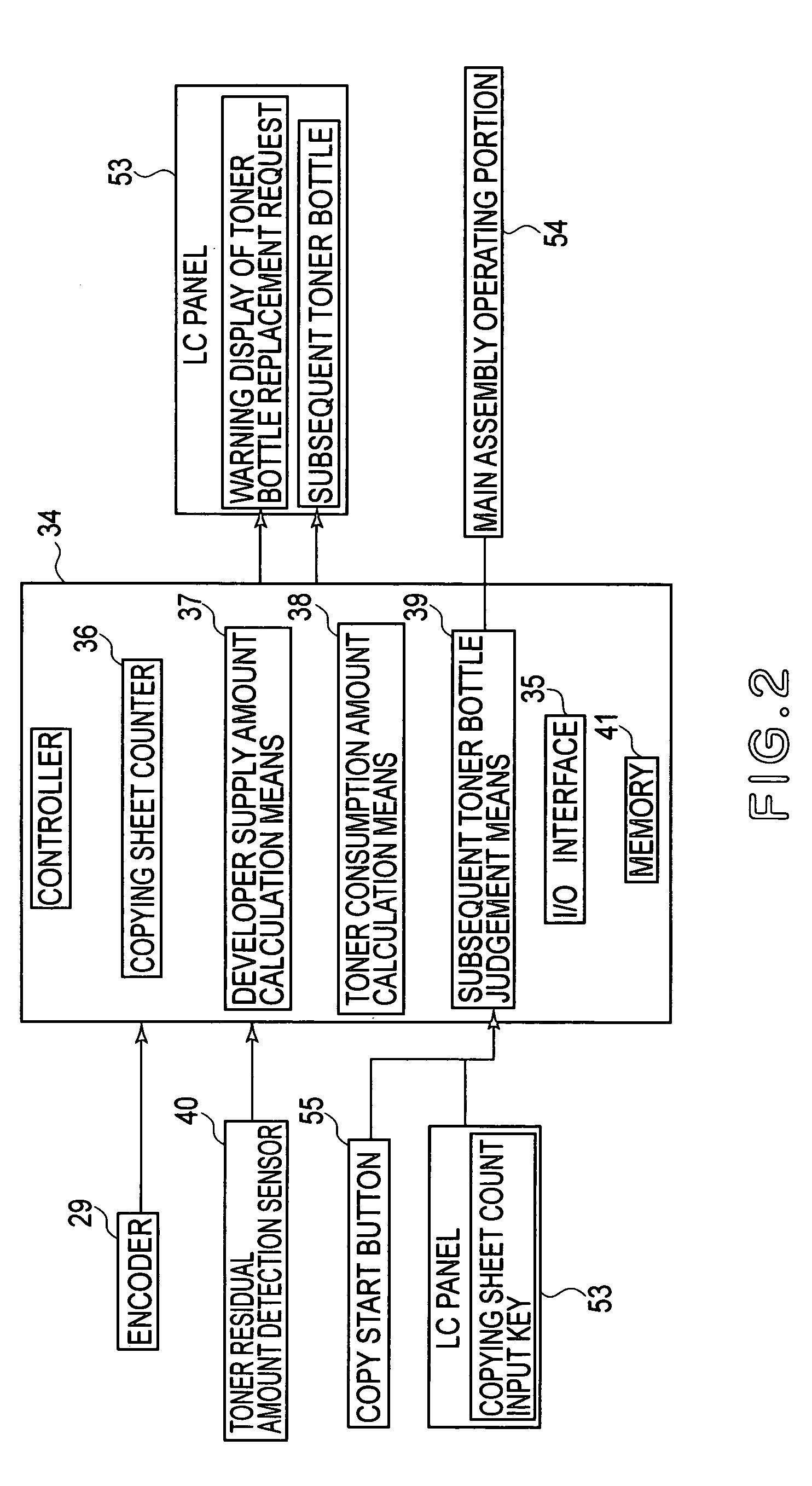
[0091]In this embodiment, the constitution of the controller 34 as the selection means for the toner bottle 25 in Embodiment 1 is changed to that of a controller 34 shown in FIG. 2.

[0092]In this embodiment, an integrated value of a copying sheet counter 36 is not cancelled even when a toner bottle 25 is replaced and the number of copying sheet is further integrated as it is. In other words, the resultant integrated value means the number of copying sheets counted from the time of shipping.

[0093]In the controller 34, a memory (storage means) 41 is disposed, and a toner consumption amount calculated at the time of replacing the toner bottle 25 is integrated in the memory 41 every replacement of toner bottle 25. As a result, a total amount of toner consumption from the time of shipping to the time of previous replacement of toner bottle 25 is stored in the memory 41.

[0094]Other constitutions of this embodiment are identical to those in Embodiment 1, so that members (means) identical to...

embodiment 3

[0104]In this embodiment, similarly as in Embodiments 1 and 2, it is possible to selectively dispose a plurality of toner bottles 25 of different types. However, in this embodiment, a supply table used for supplying developer to a developing apparatus 3 is changed depending on the types of the toner bottles 25. The supply table means a table which is provided in order to adjust a toner supply amount depending on an output of a toner concentration sensor 51 and shows a relationship between the output of the toner concentration sensor 51 set in the controller 34 and an amount (number) of rotation of a supply screw 28a detected by an encoder 29. The rotation amount of the supply screw 28a corresponds to a supply amount of developer.

[0105]The toner concentration sensor 51 for detecting a mixing weight ratio of toner particles to developer (toner particles and a carrier) of the developer contained in a developer container 24 (hereinafter, referred to as a “T / D ratio” is provided to the d...


PUM


Abstract

An image forming apparatus includes a developing device for developing an electrostatic latent image, formed on an image-bearing member, with toner; a developer supply container which contains developer containing toner and a carrier and is detachably mountable to a main assembly of the image forming apparatus; developer supply means for supplying the developer contained in the developer supply container to the developing-device; and developer discharge means for permitting discharge of the developer in the developing device to the outside of the developing device. To the image forming apparatus, one of plural kinds of developer supply containers containing developers having different carrier ratios in the developers is selectively mountable. The image forming apparatus further comprises notification means for providing notification of the kind of the developer supply container to be selected on the basis of information on deterioration of the carrier when the developer supply container is replaced.

Description

FIELD OF THE INVENTION AND RELATED ART[0001]The present invention relates to an image forming apparatus which adopts an electrophotographic process, an electrostatic recording process, etc., and a management system thereof. Particularly, the present invention relates to an image forming apparatus which is provided with a developing means including a two-component developer containing toner and a carrier and provides a good replacement maintenance performance of a developer supply container, and a management system, for managing the image forming apparatus, which systematizes data communication and network management.[0002]In a conventional image forming apparatus, a developing means (developing apparatus) for visualizing an electrostatic latent image on a surface of an image bearing member with a two-component developer containing toner and a carrier, i.e., effecting development has been frequently used.[0003]In such a developing apparatus of the two-component development type, the ...

Claims


Application Information

Patent Timeline
Patent Type & Authority Patents(United States)
IPC IPC(8): G03G15/08G03G15/00G03G21/00
CPCG03G15/0855G03G15/0853G03G15/0865G03G15/0877G03G15/0849G03G2215/0602G03G2215/066G03G2215/0888
Inventor KOJIMA, RYUICHIYAHAGI, TAKASHI
Owner CANON KK
Learn More