
Configurable high-speed serial links between components of a network device

a high-speed serial link and network device technology, applied in the field ofcon, can solve the problems of high latency of bus segments and complicated arbitration, and achieve the effect of low-latency communication

Active Publication Date: 2007-07-10
CISCO TECH INC
View PDF5 Cites 7 Cited by
  • Summary
  • Abstract
  • Description
  • Claims
  • Application Information

AI Technical Summary

Benefits of technology

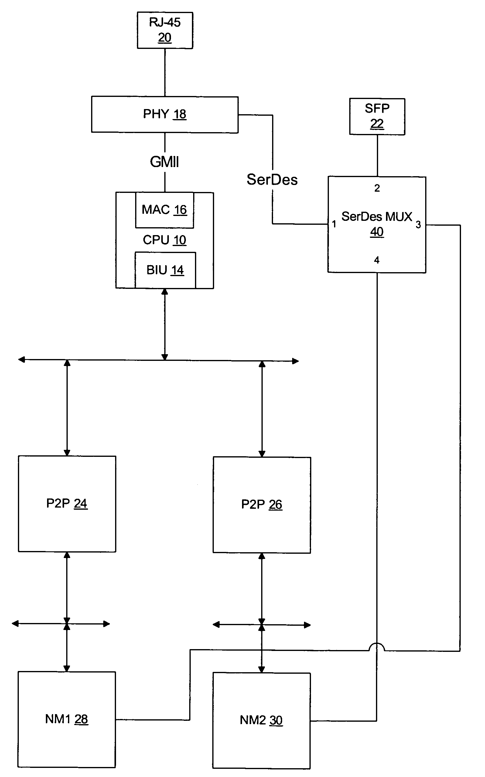
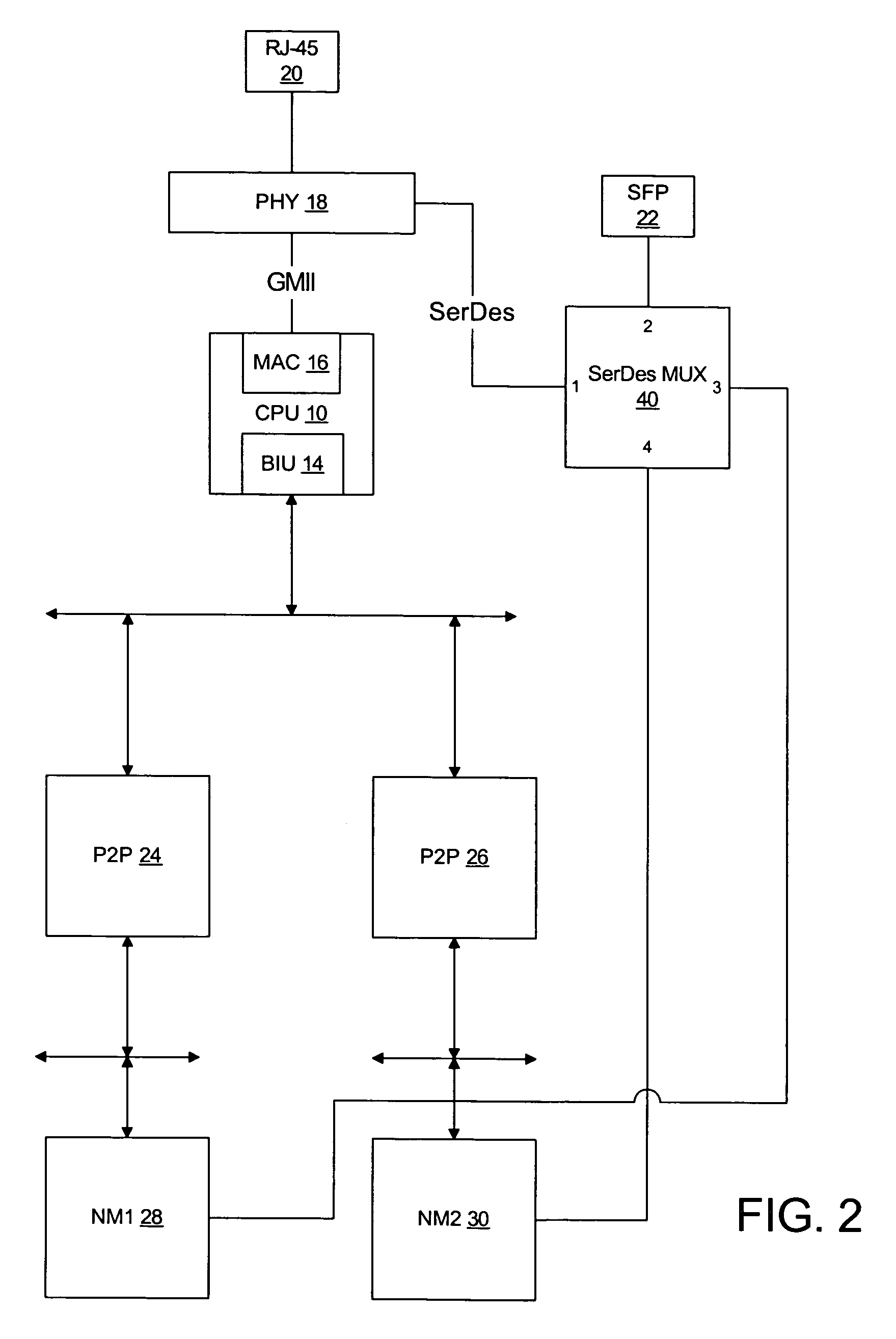
The invention is a network device that includes a non-blocking switch that can connect different data ports. One embodiment of the invention allows for a high-speed serial link between network modules using the switch, which reduces latency and improves communication. Another embodiment allows for a high-speed serial link between the network module and a GE slot using the switch. Overall, the invention provides improved network performance and efficiency.

Problems solved by technology

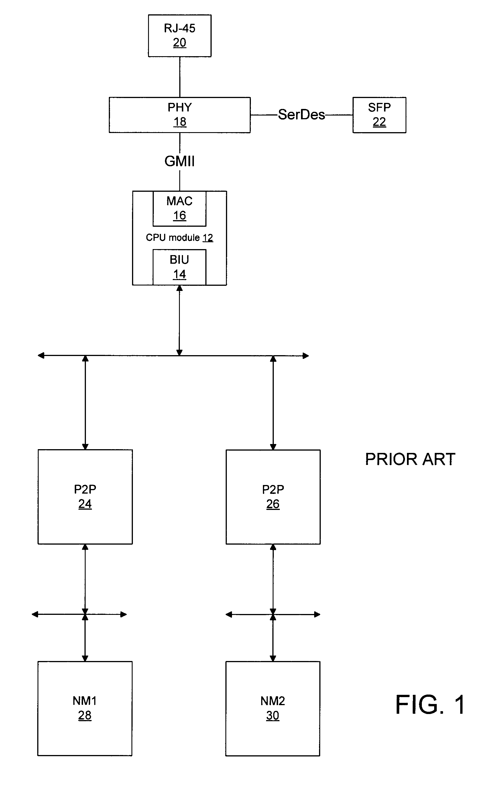
However, since the PCI bus system is hierarchical in the sense that communication between devices is managed by the P2P bridges and devices on different segments must be managed by multiple P2P bridges, there can be high latency when bus segments or busy and arbitration is complicated.
However, many network devices utilize a distributed processing model where processing is performed on the network modules without the use of the CPU to avoid latency due to the need to access the CPU and memory through multiple P2P bridges and bus segments.

Method used


Image

  • Configurable high-speed serial links between components of a network device
  • Configurable high-speed serial links between components of a network device
  • Configurable high-speed serial links between components of a network device

Examples


Embodiment Construction

[0016]Reference will now be made in detail to various embodiments of the invention. Examples of these embodiments are illustrated in the accompanying drawings. While the invention will be described in conjunction with these embodiments, it will be understood that it is not intended to limit the invention to any embodiment. On the contrary, it is intended to cover alternatives, modifications, and equivalents as may be included within the spirit and scope of the invention as defined by the appended claims. In the following description, numerous specific details are set forth in order to provide a thorough understanding of the various embodiments. However, the present invention may be practiced without some or all of these specific details. In other instances, well known process operations have not been described in detail in order not to unnecessarily obscure the present invention.

[0017]The invention will now be described with reference to various embodiments implemented in a network ...


PUM


Abstract

A system for selectively forming high-speed serial connections between various components of a network device that includes a multiplexing switch coupled a GE slot and to the high speed serial interfaces of a PHY and at least two network devices. The switch can be programmed to connect the serial interfaces of the two network modules to provide a high-speed, low-latency serial link between the two network modules. Alternatively, the serial interface of a network module can be connected to the GE slot to provide a high-speed, low-latency serial link between the network module and the GE slot.

Description

RELATED APPLICATIONS[0001]This application claims priority from a provisional application entitled A METHOD AND SYSTEM FOR CONFIGURING HIGH-SPEED SERIAL LINKS BETWEEN COMPONENTS OF A NETWORK DEVICE, filed Oct. 4, 2004, Ser. No. 60 / 615,909, which is hereby incorporated by reference for all purposes.BACKGROUND OF THE INVENTION[0002]Network devices, such as routers and switches, often utilize modules and cards to implement interfaces and ports to provide interconnectivity to other network devices and allow the network device to be configured to meet the particular requirements of a particular network node.[0003]The network devices must provide a switching fabric to allow the transfer of data and other information between modules and cards. A common implementation of a switching fabric is a bus system, such as the PCI bus, where PCI bus defines an interface between a host CPU and a number of peripheral devices. The number of peripheral devices connected can be increased by utilizing PCI...

Claims


Application Information

Patent Timeline
Patent Type & Authority Patents(United States)
IPC IPC(8): G06F13/00
CPCG06F13/4022
Inventor JENSEN, NIELS-PEDER MOSEGAARDSHEN, NANCYNAUMANN, JOEL CRAIG
Owner CISCO TECH INC
Learn More