Eye target apparatus

a target apparatus and eye technology, applied in the field of eye target apparatus, can solve the problems of eye surgery more difficult, eye movement uncontrollable, additional medical complications,

Inactive Publication Date: 2007-07-17
BISCARDI HENRY M
View PDF16 Cites 48 Cited by
  • Summary
  • Abstract
  • Description
  • Claims
  • Application Information

AI Technical Summary

Benefits of technology

[0007]Broadly, the present invention is an eye target apparatus for use in helping to control an operative eye focus line of sight axis position during medical procedures on the operative eye. The eye target apparatus includes a housing for occluding substantially all visual perception from an exterior environment for a non operative eye. The housing also includes a cover, the cover also having an internal surface that forms a plane positioned approximately perpendicular to the non operative eye focus line of sight axis. Also included is a visually perceptible element that is adjacent to the cover internal surface being in visual communication with the non operative eye. In addition, included is a means for moving the visually perceptible element within the plane to any selected position. The eye target apparatus is operational to help the non operative eye focus on a selected line of sight focus axis position upon the visually perceptible element with the result in assisting in the operative eye achieving a stable selected line of sight focus axis position with minimal operative eye movement from the selected line of sight focus axis position.

Problems solved by technology

Depending upon the medical procedure performed on the operative eye and the level of anesthesia, the bright high-intensity operative lighting that is focused upon the operative eye, that typically has diminished visual acuity from the medical procedure, can be disorientating and uncomfortable for the awake patient in addition to possibly causing the operative eye to change its focus line of sight position unexpectedly and / or cause the operative eye to move uncontrollably, making the eye surgery more difficult and lengthy potentially causing additional medical complications.
Although, the aforementioned problem is recognized, the prior art has not directly addressed this issue, however, there are some prior art devices that occlude an eye or impart various visual images to the eye for the purpose of field of vision testing, eye therapy, brain activity testing, sports timing or pacing, and the like.
Another example is in a more conventional field of vision testing device in U.S. Pat. No. 5,461,436 to Campbell that discloses an open chamber that both of the patient's eyes see and thus both of the patient's eyes see the same background color allowing color field of vision testing thus minimizing retinal rivalry interference, which is where the eye that is not the subject of the field of vision testing interferes with the vision of the eye being tested, such as when the eye not being tested is completely occluded and interferes with the vision of the eye being tested, being particularly troublesome when the patient has a dominant eye.
Additionally, in Campbell if the non tested eye was exposed to a white light background, which was found to be too bright for some patient's, was also found to affect field of vision test results.
The aforementioned prior art does not disclose a device that directly addresses the identified problems of the operative eye assuming a selected particular focus line of sight axis position and be stable in that particular focus line of sight axis position, or having a device to move the operative eye to a second selected focus line of sight axis position or positions and also helping to maintain the selected focus line of sight axis position in a stable manner for the purpose of more effective and efficient eye surgery for the patient.

Method used


Image

  • Eye target apparatus
  • Eye target apparatus
  • Eye target apparatus

Examples


Embodiment Construction

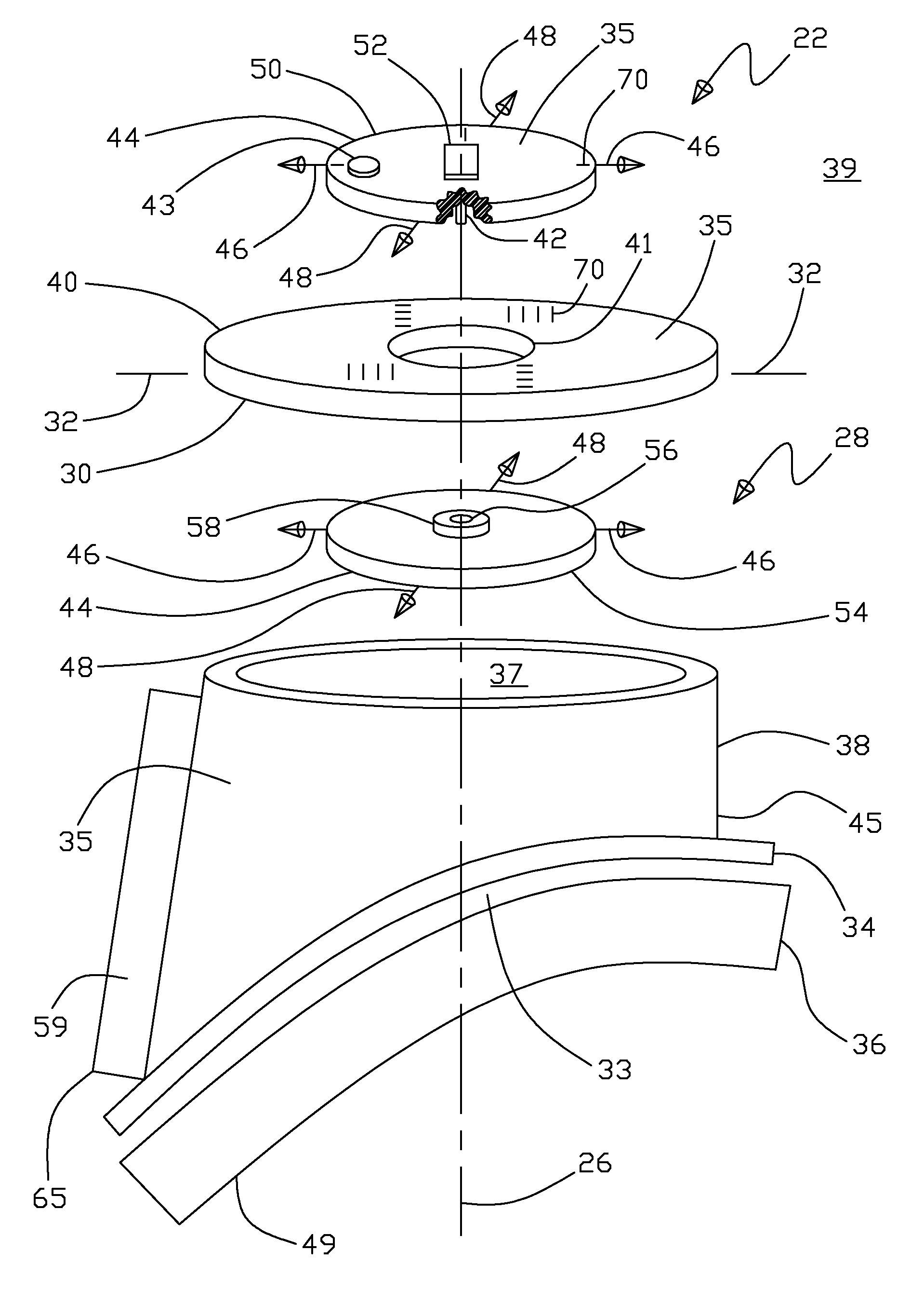
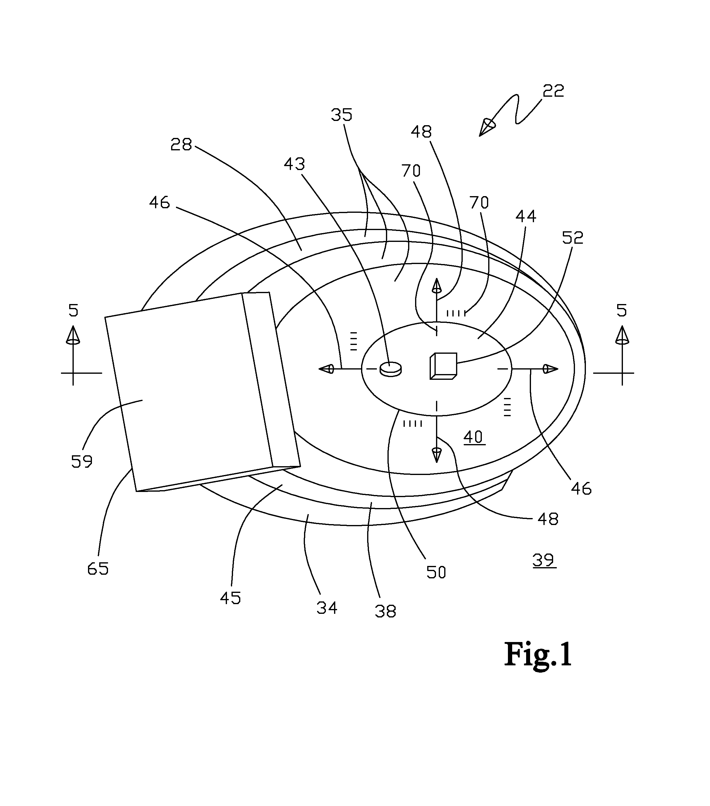
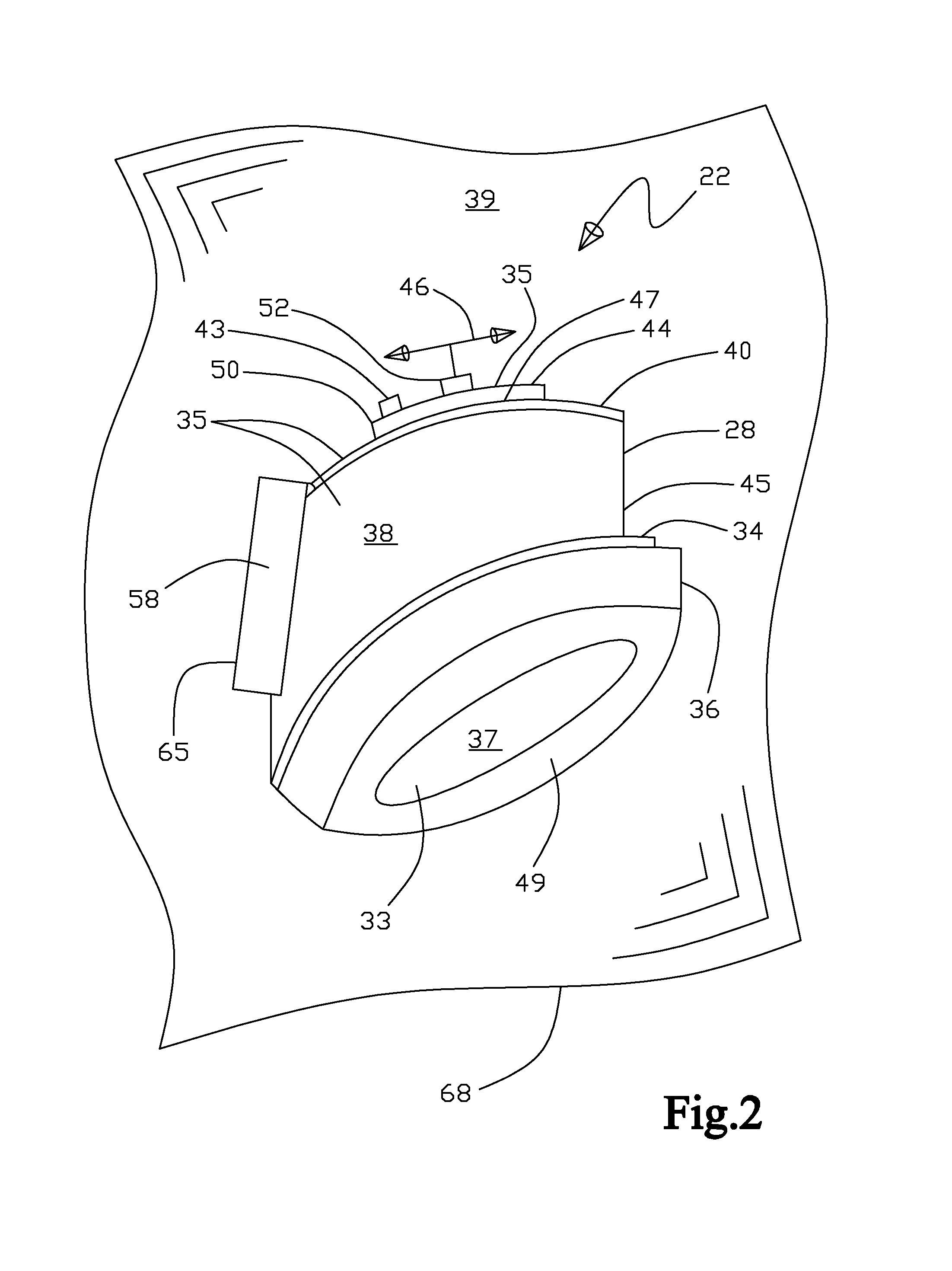
[0084]With initial reference to FIGS. 1-11, the eye target apparatus 22 and the alternative embodiment of the eye target apparatus 23 are generally described, as an eye target apparatus 22 and the alternative embodiment of the eye target apparatus 23 being for use in helping to control an operative eye 72 focus line of sight axis 74 position during medical procedures on the operative eye 72. With FIG. 1 showing a perspective view of the eye target apparatus 22 as viewed from the side opposite of the non operative eye 24 side. FIG. 2 shows a perspective view of the eye target apparatus 22 as viewed from a side elevation and FIG. 3 shows a view of the eye target apparatus 22 as viewed from the non operative eye 24 side. Further, FIG. 4 shows an exploded perspective view of the eye target apparatus 22 as viewed from a side elevation and FIG. 5 shows cross-sectional view 5-5 from FIG. 1 of the eye target apparatus 22 in use placed upon a patient's 78 facial contour 27 over the non opera...


PUM


Abstract

An eye target apparatus and method helping to control an operative eye focus line of sight position during medical procedures on the operative eye of a cooperative awake patient. The apparatus includes a housing for occluding substantially all visual perception from an exterior environment for a non operative eye, the housing including a cover, with an internal surface that forms a plane approximately perpendicular to the non operative eye line of sight axis. Also included is a visually perceptible element adjacent to the internal surface being in visual communication with the non operative eye and structure for moving the visually perceptible element within the plane to any selected position, the apparatus is operational to help the non operative eye focus on a selected line of sight position upon the visually perceptible element with the result in assisting in the operative eye achieving a stable selected line of sight position.

Description

TECHNICAL FIELD[0001]The present invention relates generally to apparatus that occludes an eye for the purpose of helping to control the positioning of a non occluded eye during medical procedures being performed upon the non occluded eye. More particularly, the present invention relates specifically to an eye target apparatus that helps control a selected focus line of sight axis position and line of sight axis position stability of the occluded eye thereby helping to control the non occluded eye or operative eye that has medical procedures performed upon it, wherein the selected focus line of sight axis position and line of sight position stability of the operative eye acts in conjunction with the occluded or non operative eye by both of the patient's eyes generally acting in coordination.BACKGROUND OF INVENTION[0002]There are a number of medical procedures that are performed on a patient's eye (termed operative eye) such as cataract removal, lens implants, vision corrective surge...

Claims


Application Information

Patent Timeline
Patent Type & Authority Patents(United States)
IPC IPC(8): A61B3/10A61B17/00A61B3/02A61B3/14A61F2/16A61F9/007A61F9/008
CPCA61F9/007A61F2009/00846
Inventor BISCARDI, HENRY M.
Owner BISCARDI HENRY M
Why Eureka
Try Eureka