Tactile panel

a technology of a tactile panel and a spherical plate, which is applied in the direction of electromechanical transducers, instruments, transducer diaphragms, etc., can solve the problems of degrading the effective thrust force that contributes to the vibration, the technique disclosed in document 1 cannot be applied to the prevention of etc., to prevent the decrease of the thrust force of the vibration panel, the effect of easy assembly

Active Publication Date: 2007-07-17
FUJITSU COMPONENENT LTD
View PDF8 Cites 12 Cited by
  • Summary
  • Abstract
  • Description
  • Claims
  • Application Information

AI Technical Summary

Benefits of technology

[0011]The present invention has been made in view of the above-mentioned circumstances and provides a tactile panel that can prevent the decrease in a thrust force of a vibration panel and that can be assembled readily.

Problems solved by technology

Nevertheless, as far as the vibration panel is pushed and secured from top and bottom, the thrust force is inevitably absorbed by the vibration panel holding members every time the vibration panel vibrates up and down.
This results in a problem in that the effective thrust force that contributes to the vibration is degraded.
Therefore, the technique disclosed in Document 1 cannot be applied to the prevention of the decrease in the thrust force of the vibration panel.
Thus, there arises another problem in that it is not easy to arrange the pair of permanent magnets at optimal positions and the assembling process also becomes complicated.

Method used


Image

  • Tactile panel
  • Tactile panel
  • Tactile panel

Examples


Embodiment Construction

[0018]A description will now be given, with reference to the accompanying drawings, of embodiments of the present invention.

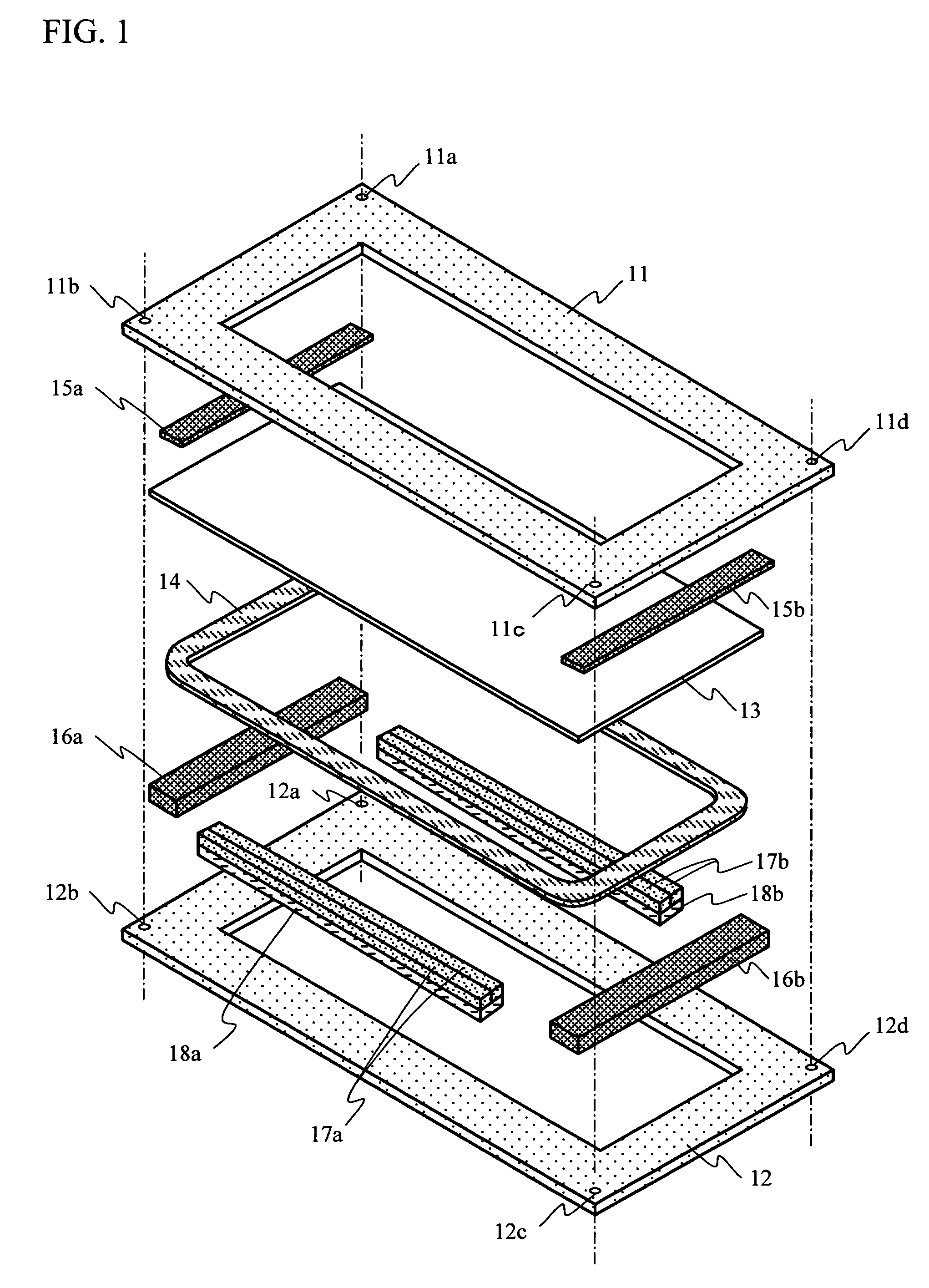
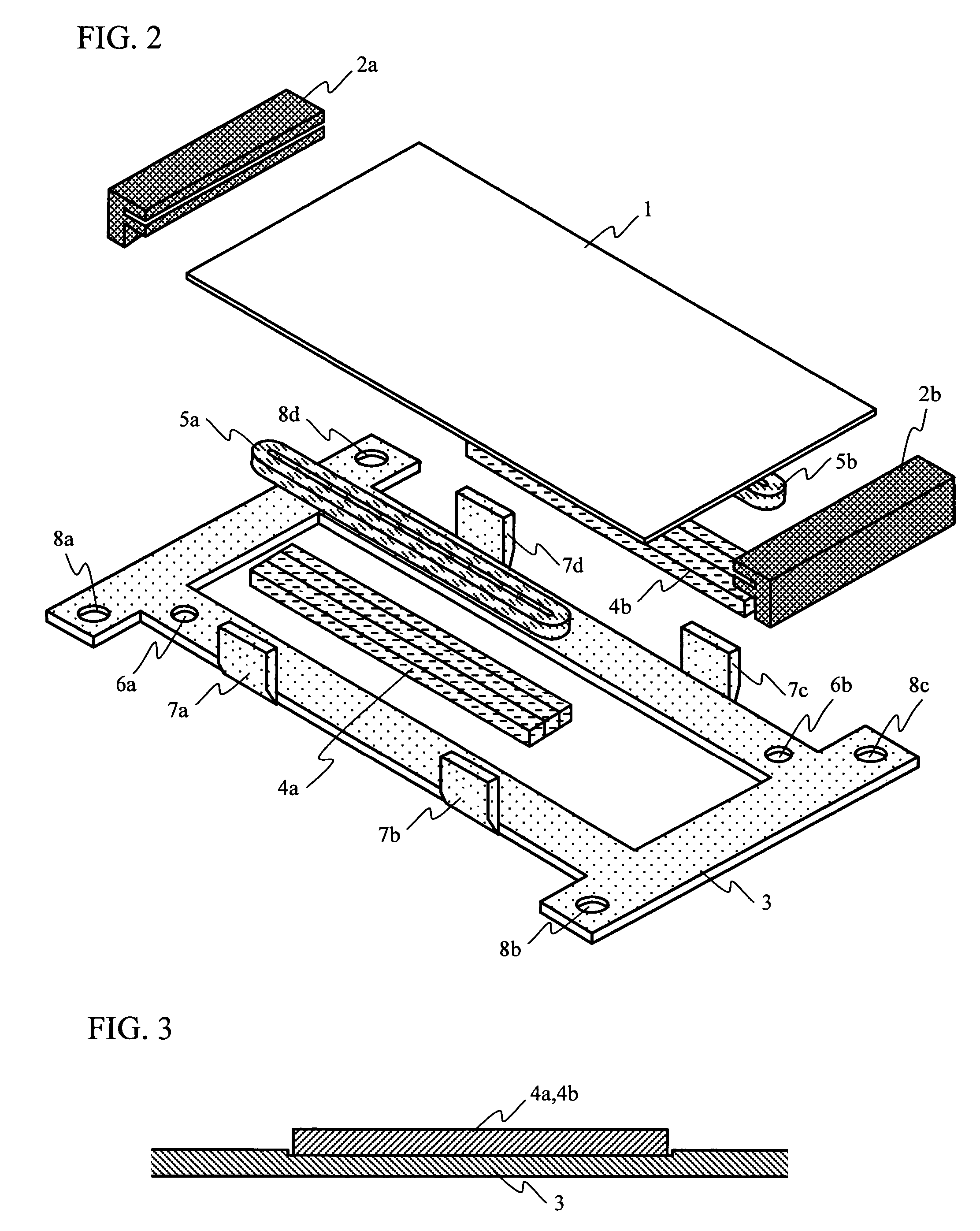
[0019]FIG. 2 schematically illustrates a tactile panel of the present invention, is also an exploded perspective view of constructional members of the tactile panel. A vibration panel 1 is a plane plate of a rectangular shape. The vibration panel 1 is inserted into panel holding members 2a and 2b so that the panel holding members 2a and 2b can hold rims on short sides of the vibration panel 1. The panel holding members 2a and 2b are adhered and secured to given positions of a magnetic yoke 3. The panel holding members 2a and 2b hold the vibration panel in a direction perpendicular to the vibration direction. The panel holding members 2a and 2b are made of an elastic material as represented by a rubber such as nitrile rubber. The elastic material is employed so as not to decrease the thrust force applied to the vibration panel 1.

[0020]The yoke 3 is formed into a...


PUM

PropertyMeasurementUnit
circumferenceaaaaaaaaaa
sizesaaaaaaaaaa
thrust forceaaaaaaaaaa

Abstract

A tactile panel includes a vibration panel, a yoke provided to face the vibration panel, drive coils secured on a circumference of the vibration panel, and a set of permanent magnets arranged between the vibration panel and the yoke. The vibration panel is held by panel holding members, into which both sides of the vibration panel are inserted in a direction substantially perpendicular to a vibration direction of the vibration panel.

Description

BACKGROUND OF THE INVENTION[0001]1. Field of the Invention[0002]This invention generally relates to tactile panels, and more particularly, to a tactile panel that can prevent a decrease in a thrust force of a vibration panel and that can be assembled readily.[0003]2. Description of the Related Art[0004]FIG. 1 schematically shows a conventional tactile panel, also known as a haptic panel. FIG. 1 schematically shows a configuration of the conventional tactile panel, and is also an exploded perspective view of constructional members of the tactile panel. Referring to FIG. 1, a reference numeral 11 denotes an upper frame and a reference numeral 12 denotes a lower frame. Other members such as a vibration panel 13, as will be described later, are sandwiched and secured by the upper panel 11 and the lower panel 12 from top and bottom so as to form one unit.[0005]A drive coil 14 is provided just below the vibration panel 13, and is bonded to the circumference of the vibration panel 13 as go...

Claims


Application Information

Patent Timeline
Patent Type & Authority Patents(United States)
IPC IPC(8): H02K41/00
CPCH04R7/045
Inventor FUJII, NOBORUAKIEDA, SHINICHIROAKAMA, JUNICHINAKAMURA, AKIO
Owner FUJITSU COMPONENENT LTD
Why Eureka
Try Eureka