
Tool and accessory container with inner grid system

a tool and accessory container technology, applied in the field of tool and accessory container with inner grid system, can solve the problems of limiting the application of the tool case, and limiting the number of inserts,

Inactive Publication Date: 2007-07-24
BLACK & DECKER INC
View PDF90 Cites 93 Cited by
  • Summary
  • Abstract
  • Description
  • Claims
  • Application Information

AI Technical Summary

Benefits of technology

This solution provides users with individual control over tool package location and selection, accommodating various sizes and orientations, enhancing organizational flexibility and usability.

Problems solved by technology

Molds or tooling for the case members are typically not easily reconfigured to accommodate multiple case designs.
For obvious reasons, tool cases using preformed inserts are limited to specific tools / accessories and their sizes, limiting the applications of the tool case.
Providing multiple preformed inserts to accommodate multiple tool case applications requires the cost and complexity of developing tooling and the storage / inventory control / numbering for these multiple inserts.
This limits the organizational arrangement and potentially the sizes and types of tools / accessories within the tool case.

Method used


Image

  • Tool and accessory container with inner grid system
  • Tool and accessory container with inner grid system
  • Tool and accessory container with inner grid system

Examples


Embodiment Construction

[0025]The following description of the preferred embodiments is merely exemplary in nature and is in no way intended to limit the invention, its application, or uses.

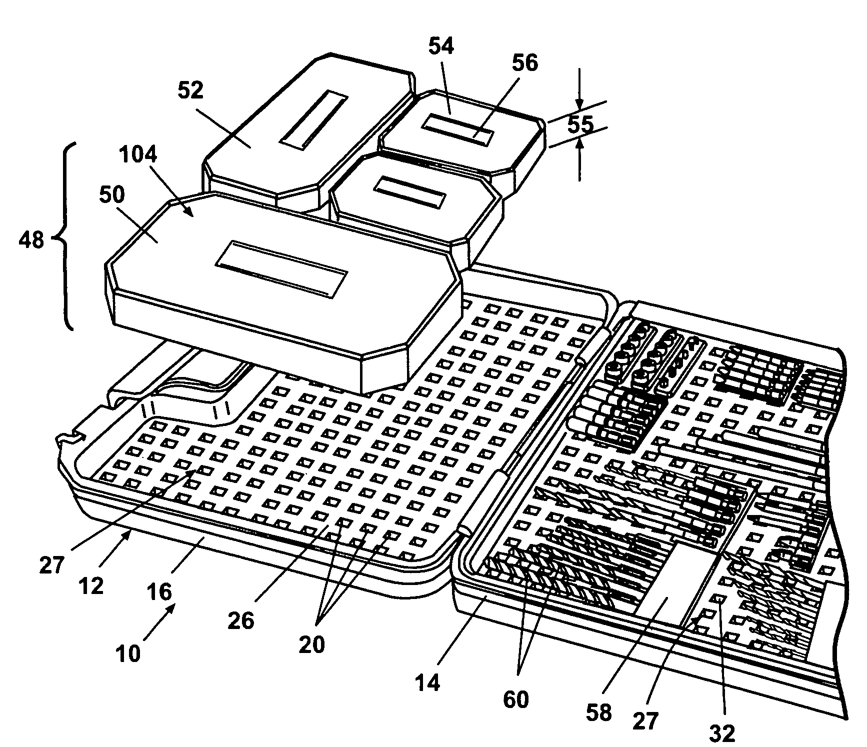
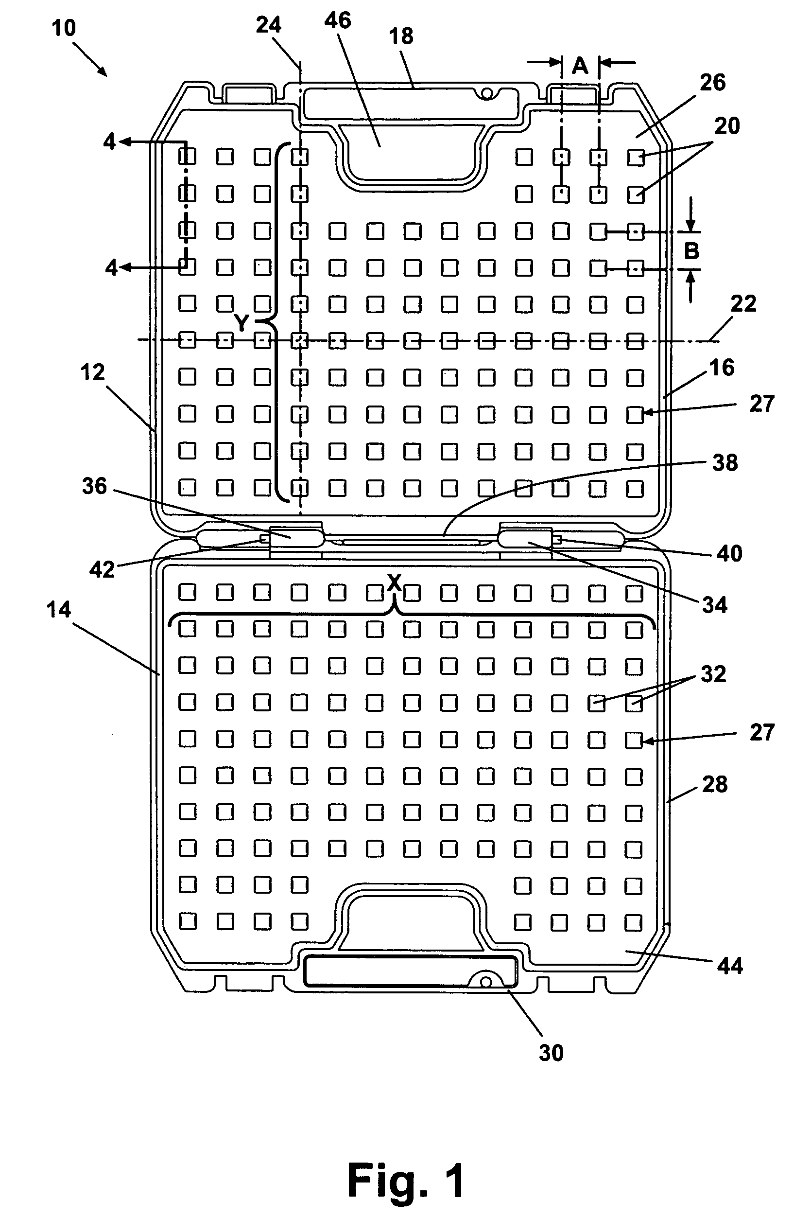
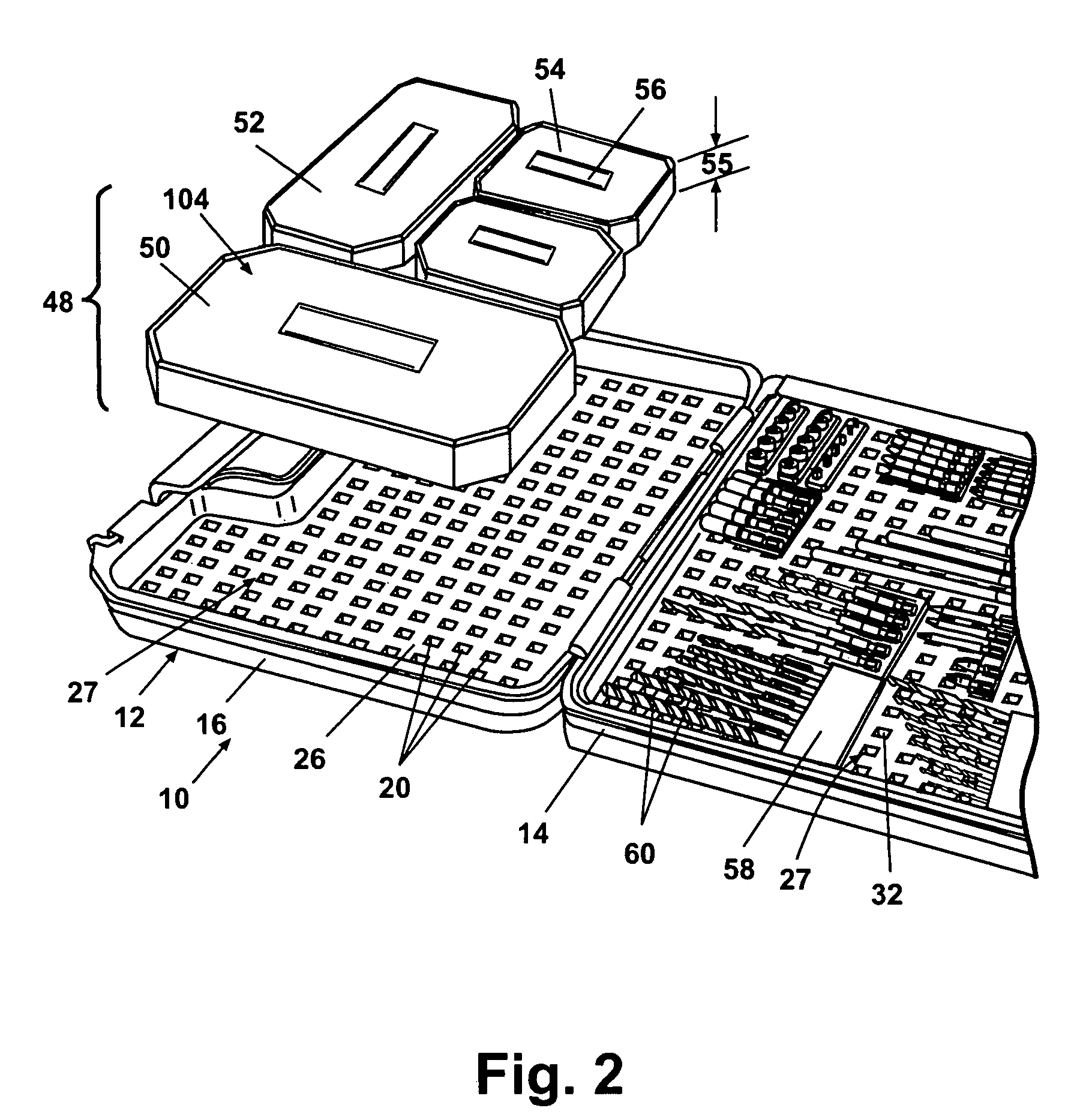
[0026]According to a preferred embodiment of the present invention and referring generally to FIG. 1, a tool container 10 includes a first portion 12 and a second portion 14. First portion 12 includes a perimeter wall 16, a first handle portion 18, and a plurality of receptacles 20. In one aspect of the invention, each of the receptacles 20 are substantially rectangular in shape and are arranged as subsets of receptacles in each of a plurality of subset rows 22 and subset columns 24 of receptacles 20. The receptacles 20 in each subset row 22 are generally arranged with equivalent row spacing “A”. Similarly, receptacles 20 in each subset column 24 are arranged with generally equivalent receptacle column spacing “B”. In one preferred embodiment of the present invention, receptacle row spacing “A” and receptacle column spa...


PUM


Abstract

A tool container includes first and second container members rotatably connected to create an inner compartment. Each member has a compartment outer wall and integrally formed perimeter walls. A grid system is created on an inner compartment facing surface adjacent at least one of the compartment outer walls. The grid system includes female receptacles arranged in each of a plurality of rows and columns. Tool packages having at least one male peg member are releasably engaged within selected receptacles providing multiple locations and orientations about the grid system for the tool packages.

Description

FIELD OF THE INVENTION[0001]The present invention relates in general to containers for storing articles and more specifically to a device and method for use of a molded plastic container for storing tools and tool accessories.BACKGROUND OF THE INVENTION[0002]Cases for storing tools or tool accessories are well known, and typically include a base in the form of an open-topped box, and usually a hinged lid, or two container halves joined by a hinge. At least one catch or clip is provided to retain the container in a closed position and a handle is also typically provided for user convenience. A cavity created between the box and lid or between the two halves provides space for storage of individual tools and / or tool accessories including driver heads, etc. Frequently, an insert is positioned within the cavity which is preformed having a plurality of outline shapes or forms of the tools or accessories intended to be stored. Each tool or accessory is positioned within these preformed, u...

Claims


Application Information

Patent Timeline
Patent Type & Authority Patents(United States)
IPC IPC(8): B65D85/28B65D21/02
CPCB25H3/003B25H3/023
Inventor BRUNSON, MARK EWIKLE, DAVID LERVIN, JENNIFER R
Owner BLACK & DECKER INC
Learn More