
Calorimetric detector for measuring the energy of electrons and photons

a detector and electron and photon technology, applied in the field of scintillator materials in nuclear or high energy physics, can solve the problems of no longer being used types, more and more restrictions are applied to the design of calorimeters, etc., and achieve the effect of high density

Pending Publication Date: 2022-10-13
CRYTUR SPOL SRO
View PDF0 Cites 1 Cited by
  • Summary
  • Abstract
  • Description
  • Claims
  • Application Information

AI Technical Summary

Benefits of technology

The patent text describes a new design for a calorimeter that allows for better absorption of energy. This is achieved by using a tungsten matrix shell with a inner cross-section of 1 pixel. The design also includes a protective metal frame made of stainless steel, which provides a sufficient shield while being thinner and lighter than other frames. These features make the calorimeter smaller in size and suitable for use in calorimeters of multiple sizes.

Problems solved by technology

Due to high radiation hardness limitations, more and more restrictions are applied to the calorimeter design.
Those types are no longer used since they are not radiant enough.

Method used


Image

  • Calorimetric detector for measuring the energy of electrons and photons
  • Calorimetric detector for measuring the energy of electrons and photons
  • Calorimetric detector for measuring the energy of electrons and photons

Examples


Embodiment Construction

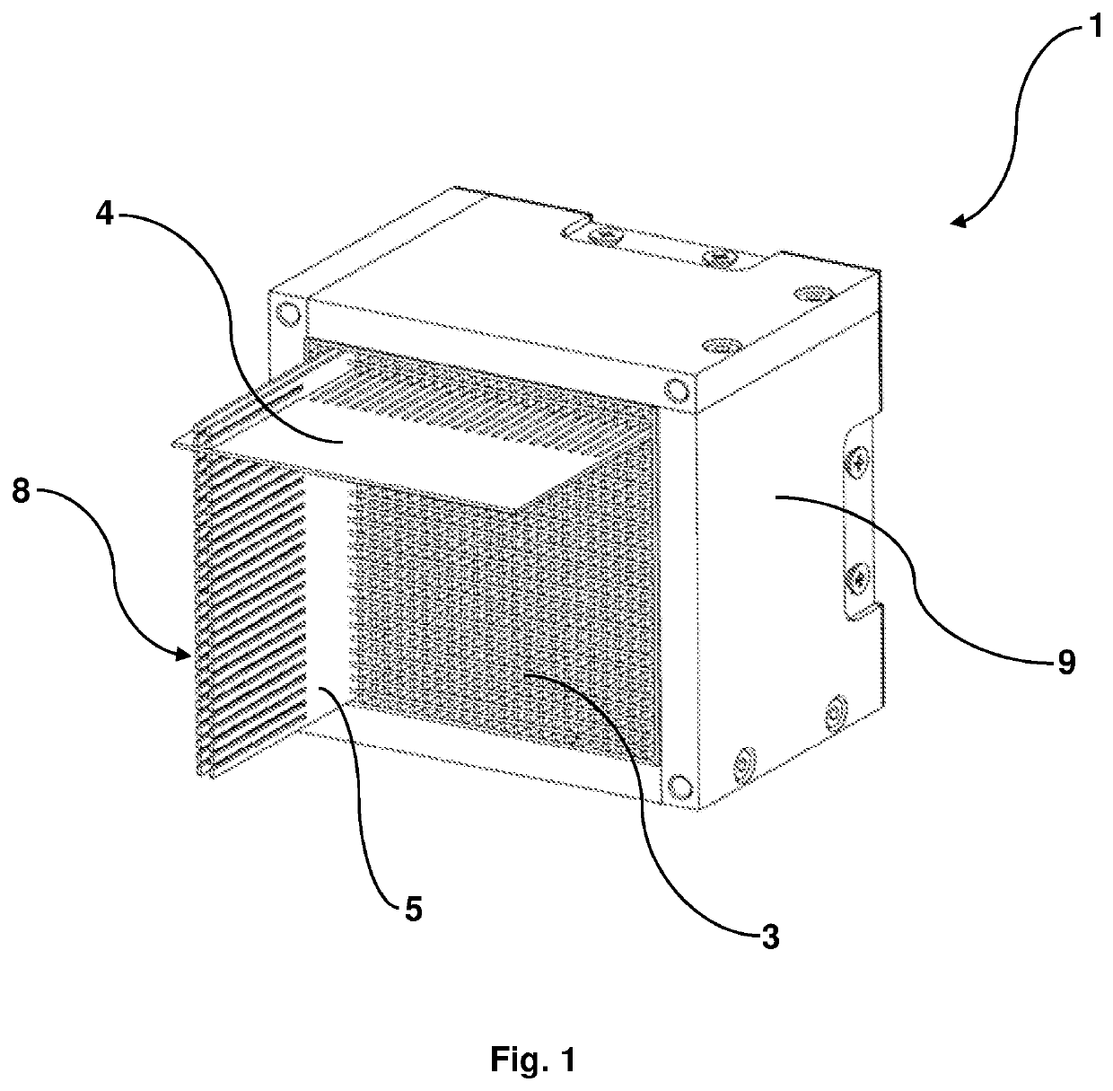
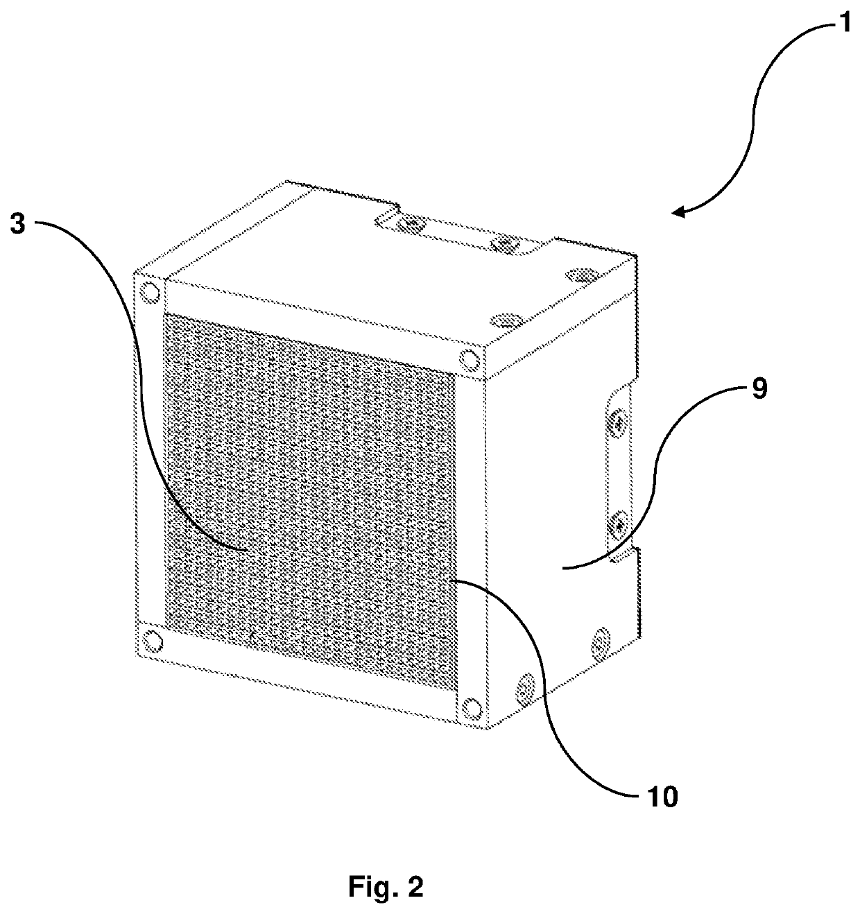
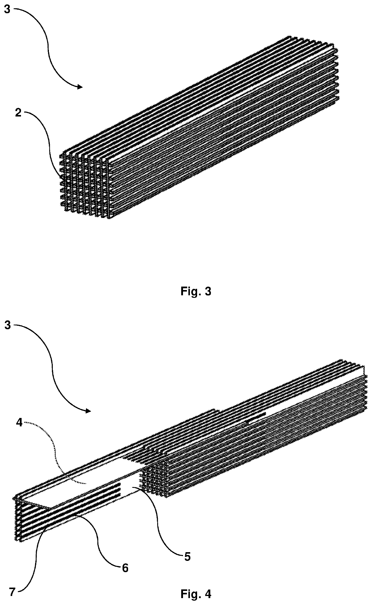
[0024]This invention proposes a calorimetric detector 1 comprising pure tungsten matrix 3 combined with single crystal fibers as scintillating fibers 2, where the scintillating fibers 2 were used to collect and transport the light. The nature of the design was flexible and it was optimized in accordance with the type of particle and shower which needed to be detected.

[0025]The shower length of the particles was estimated via simulation and it was described mainly by two parameters, as Moliere radius and the radiation length X0 are. A measurement of the transverse size, integrated over the full shower depth was given by the Molire radius (RM) which was approximated by RM(g / cm2) by the following equation:

RM(gcm2)≅21⁢ MeV⁢X0∈(MeV).

[0026]The shower shape was given by the following graph:

[0027]The electromagnetic showers, e.g., their longitudinal and lateral sizes are described in terms of the radiation length X0, which depends on the characteristics of the material:

X0(gcm2)≅716⁢ g⁢...


PUM


Abstract

A calorimetric detector (1) for measuring energy of electrons and photons comprises a light energy absorber and scintillating fibers (2). The absorber is formed of a tungsten matrix (3), comprising a first assembly (4) and a second assembly (5) of parallel tungsten plates. The first assembly (4) is perpendicular to the second assembly (5) forming a grid, while each plate is in one half formed by alternating teeth (6) and gaps (7). The first assembly's (4) plates fit detachably with their teeth (6) into the gaps (7) of the second assembly (5) and vice versa. Spaces between the plates of the first assembly (4) and the second assembly (5) form longitudinal sections (8) with inner cross-section size of one pixel. The scintillating fibers (2) are longitudinally arranged, made of a single crystal material. The tungsten matrix (3) is in a protective metal frame (9) having tungsten inner walls (10).

Description

FIELD OF THE INVENTION[0001]The present invention generally concerns scintillator materials in nuclear or high energy physics in calorimetry for measuring energy deposition. The present invention mainly concerns a calorimetric detector for measuring the energy of electrons and photons, which uses those scintillator materials.BACKGROUND OF THE INVENTION[0002]A calorimeter is an experimental apparatus for measuring the energy of particles. The essential parts of the calorimeter are namely a source, a detector, a face cover, a reflector and a readout electronics. The detector furthermore comprises an absorber and scintillating fibers. Particles enter the calorimeter and initiate a particle shower energy while the particles' energy is deposited in the calorimeter, collected, and measured. calorimeters are segmented transversely to provide information about the direction of the particle, energy deposited and longitudinal segmentation can provide information about the identity of the part...

Claims


Application Information

Patent Timeline
IPC IPC(8): G01T1/20G01T1/202
CPCG01T1/201G01T1/2023G01T1/006
Inventor HOUZVICKA, JINDRICHSYKOROVA, SILVIAHRADECKY, PATRIK
Owner CRYTUR SPOL SRO
Learn More