Valve stem lifter

a technology of valve stem and valve body, which is applied in the direction of valve housing, valve operating means/release devices, mechanical equipment, etc., can solve the problem of limiting the operation range of the valve for which it can be used, and achieve the effect of reliably opening and closing multiple valve sizes and being highly versatil

Inactive Publication Date: 2022-02-03
VANZANDT CONTROLS LLC
View PDF0 Cites 0 Cited by
  • Summary
  • Abstract
  • Description
  • Claims
  • Application Information

AI Technical Summary

Benefits of technology

[0011]The main objective of the present invention is to provide a highly versatile valve stem lifter that can fully and reliably open and close multiple sizes of valves without damaging the valve.

Problems solved by technology

Similar-sized prior art valve stem lifters typically provide only ¾ inches of lift per full rotation of their rotary shaft, which limits their operational range on the size of valves for which they can be used.

Method used


Image

  • Valve stem lifter
  • Valve stem lifter
  • Valve stem lifter

Examples


Embodiment Construction

[0023]Referring more particularly to the drawings which are for the purpose of illustrating preferred embodiments of the invention only, and not for the purpose of limiting same:

[0024]Throughout this disclosure, components and features of the disclosed invention may be discussed with reference to more than one illustration. A particular component or feature is given the same numeral throughout this disclosure and the accompanying illustrations.

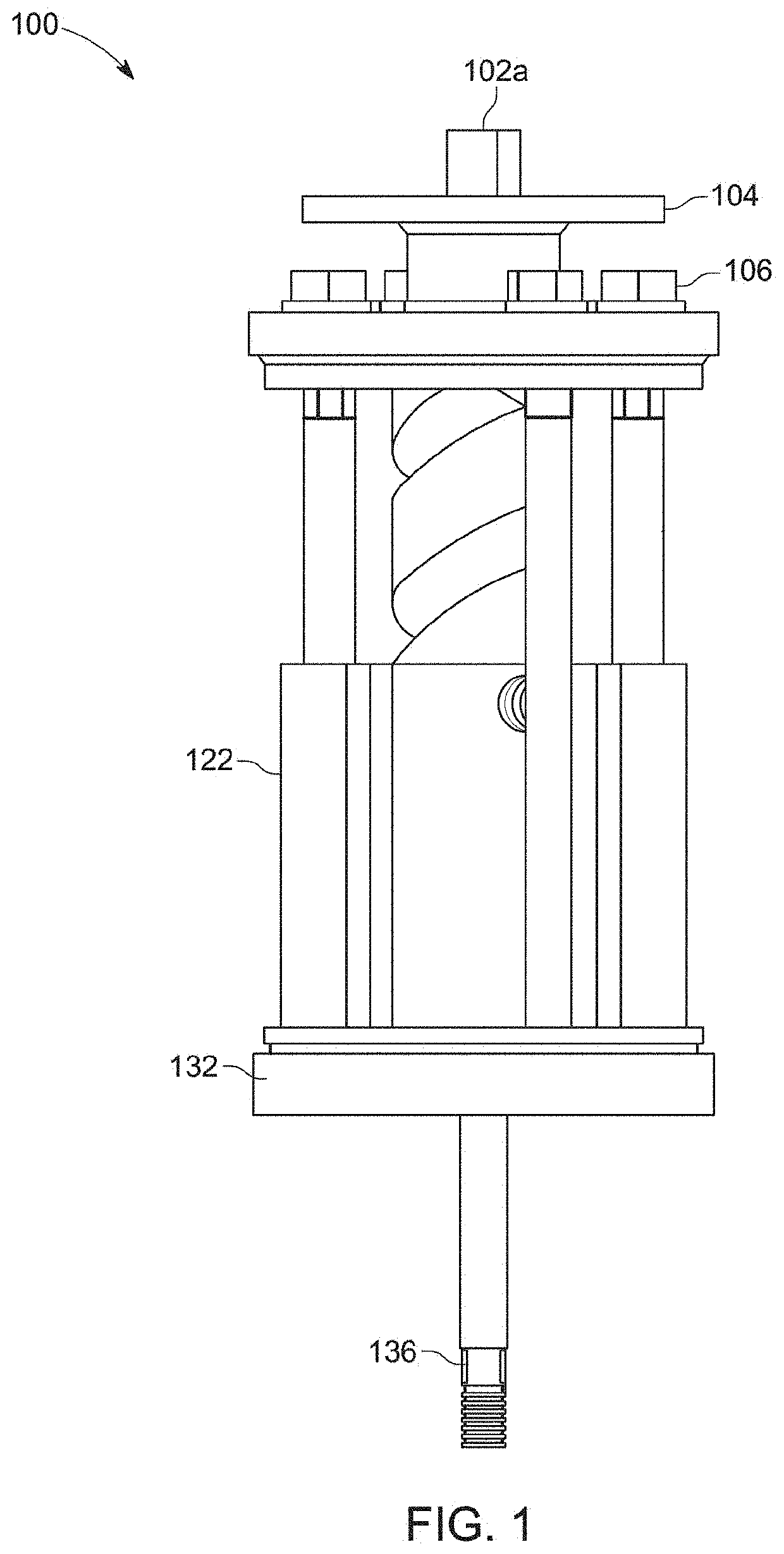
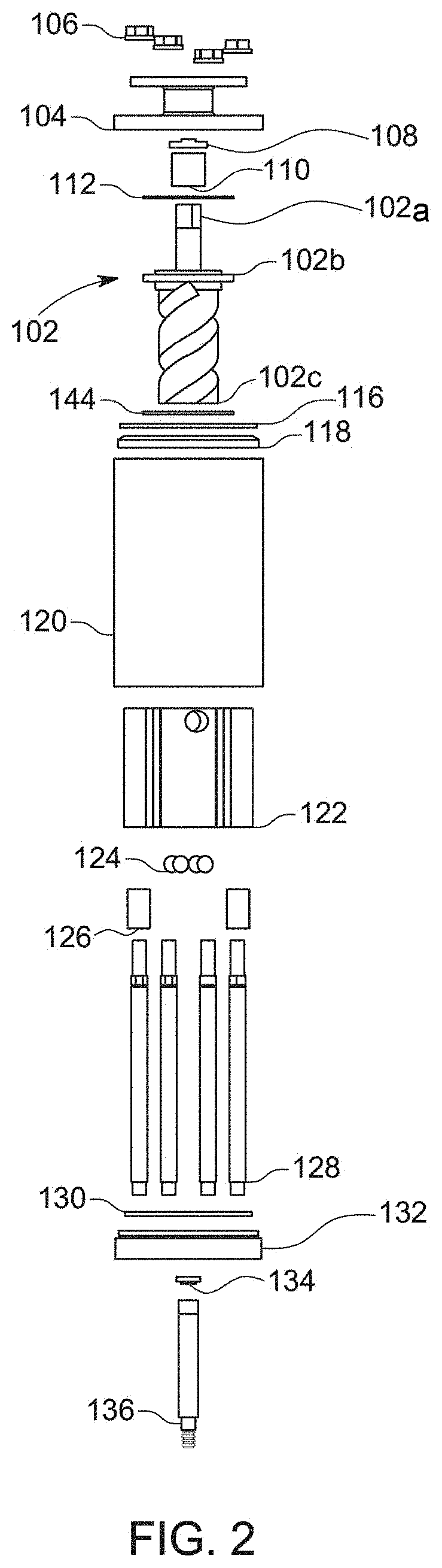
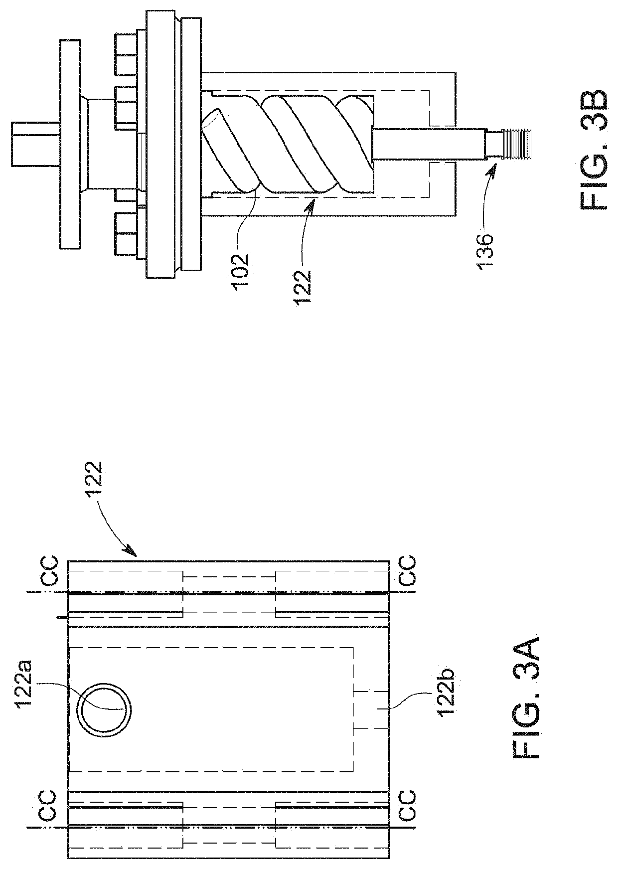
[0025]With further reference to FIGS. 1 and 2, the valve stem lifter assembly (100) generally comprises a rotary shaft (102), a flange adapter spool (104), a riser (122) and a base mounting plate (132).

[0026]The material used to form most component parts of the valve stem lifter assembly in the preferred embodiment is AISI 4140 steel, but another similar hardened metal or material that has high fatigue strength and abrasion and impact resistance could be substituted. All component parts can be manufactured using standard processes and standard...


PUM


Abstract

A valve stem lifter assembly which operates to alternatively open and close a valve, includes a rotatably mounted rotary shaft having a free end axially aligned with a pull shaft and an opposite free end axially aligned with an operator for selectively producing rotational movement of the rotary shaft and corresponding axial movement of the pull shaft. The rotary shaft is rotatably connected to a valve riser element by radius set screws positioned axially in the grooves of the rotary shaft. A plurality of guide shaft rods interconnects the riser to the valve stem lifter assembly to prevent axial separation of the riser and rotary shaft while permitting free relative rotation of the rotary shaft and linear movement of the pull shaft.

Description

CROSS REFERENCE TO RELATED APPLICATIONS[0001]This application claims priority to U.S. Provisional Patent Application Ser. No. 63059124, filed Jul. 30, 2020.BACKGROUND OF INVENTIONField of Use[0002]The present invention relates to a valve stem lifter, and more particularly to a valve stem lifter for mechanical equipment that opens a valve to allow the throttling of a fluid such as oil, natural gas, chemical or water to flow through the valve.Description of Related Art[0003]A variety of fluid flow control valves and corresponding valve actuators are utilized for either on / off control or throttling the flow of fluid, such as in a gas or oil pipeline system, or in other process fluid systems. Fluid flow control valves are typically sliding stem or rotary action control valves, and are usually operated by a valve actuator such as an electric or pneumatic actuator responding to the output of a valve positioner or valve controller instrument for accurate throttling control of the valve.[00...

Claims


Application Information

Patent Timeline
Patent Type & Authority Applications(United States)
IPC IPC(8): F16K3/24F16K3/28F16K3/316F16K27/04F16K31/50
CPCF16K3/24F16K3/28F16K3/316F16K2200/50F16K31/504F16K2200/30F16K27/041F16K31/528F16K31/50F16K31/5286
Inventor LATCH, DAVEPRIETO, ANTHONY
Owner VANZANDT CONTROLS LLC
Why Eureka
Try Eureka