
Throttle Valve Control Device and Throttle Valve Control Method

a technology of throttle valve and control device, which is applied in the direction of electrical control, process and machine control, etc., can solve the problems of limiting the range of operation of the throttle valve, the sound of collision is clearly audible, and the parts of the intermediate gear or the like of the throttle control device may wear unusually

Inactive Publication Date: 2009-08-20
HITACHI LTD
View PDF4 Cites 6 Cited by
  • Summary
  • Abstract
  • Description
  • Claims
  • Application Information

AI Technical Summary

Benefits of technology

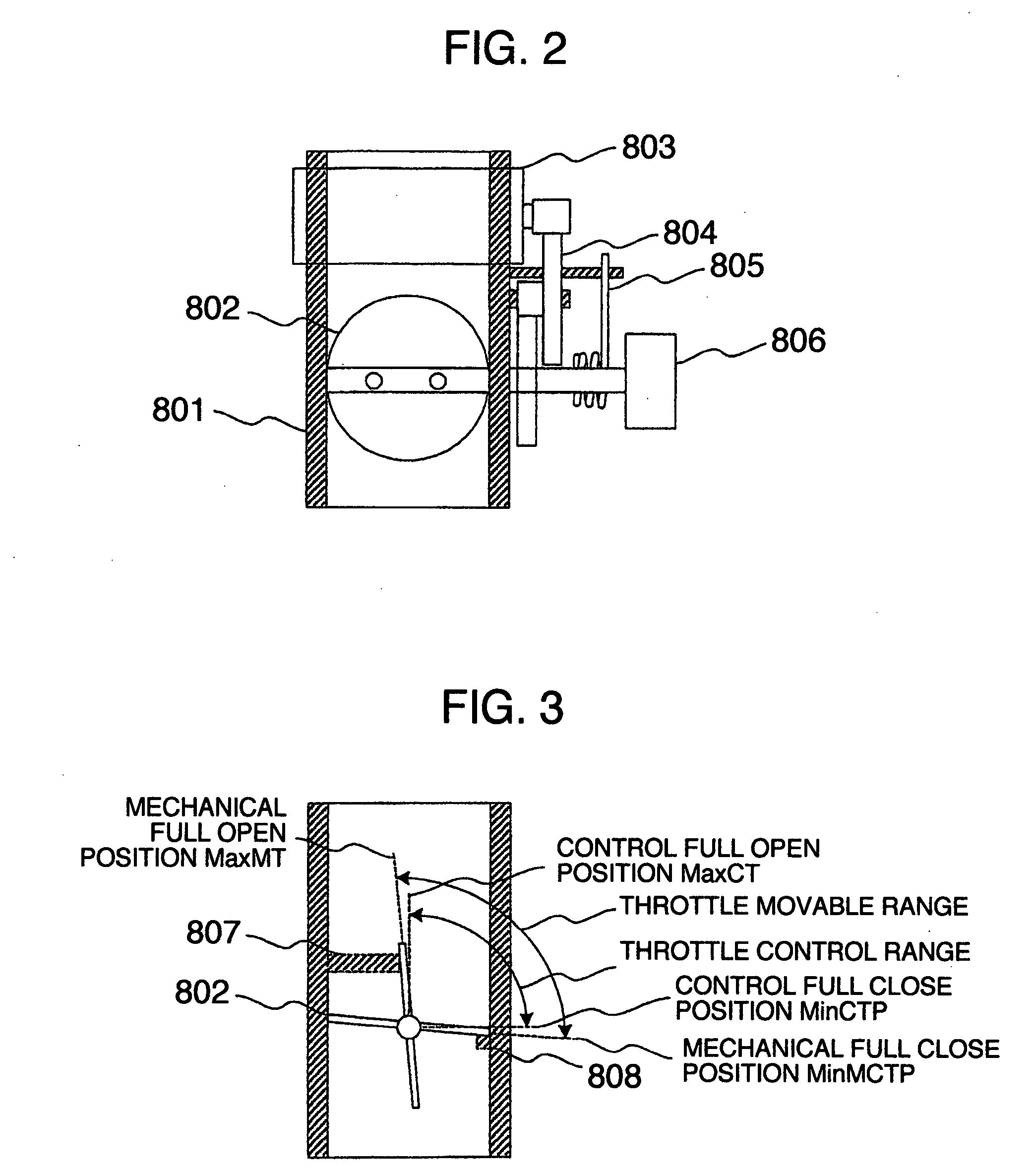
[0012]One of typical throttle valve control devices according to the present invention comprises: a throttle valve that controls an intake air flow rate of an engine; a throttle sensor that detects an opening of the throttle valve; a spring that biases the throttle valve in one arbitrary direction; a throttle stopper that limits the range of operation of the throttle valve; a stop means that stops control and driving of the throttle valve in the case where the opening of the throttle valve is equal to or greater than a predetermined value or equal to or smaller than a predetermined value; an output value judgment means that judges whether or not an output value of the throttle sensor is equal to an output value of the throttle sensor at the time when the throttle valve lies at the throttle stopper, when the control and driving of the throttle valve is stopped; and a failure judgment means that judges that the spring for biasing in the one direction has a failure if the output value of the throttle sensor differs from the output value of the throttle sensor at the time when the throttle valve lies at the throttle stopper.

Problems solved by technology

As a result, particular ones of the intermediate gears or the like of the throttle control device may unusually wear.
If the diagnosis is made when the engine is in operation, there is fear that the diagnosis will vary the power of the engine accidentally.
In the case where the diagnosis is performed when the engine is stopped, there is a problem that the sound of collision is clearly audible as compared with the engine sound and is offensive to the ear.
Therefore, there is a problem that a return spring failure cannot be detected early.
If a return spring failure cannot be detected early, there is a possibility that, in the case where the engine is supercharged with a supercharger, when the return spring 805 is broken and the throttle valve 802 accidentally vibrates or otherwise moves to the mechanical full close position MinMTP, the supercharged intake air is blocked at the throttle valve 802 and leaks from the most fragile part of an intake path.

Method used


Image

  • Throttle Valve Control Device and Throttle Valve Control Method
  • Throttle Valve Control Device and Throttle Valve Control Method
  • Throttle Valve Control Device and Throttle Valve Control Method

Examples


example 1

[0028]Now, a throttle control stopping means for reducing wear of gears, a return spring failure diagnosis process, and a process for driving a throttle valve toward a full open position according to example 1 of the invention will be described with reference to FIG. 6 (referred to as return spring failure diagnosis 1, hereinafter). The process according to the example 1 is repeated at regular time intervals.

[0029]First, in step S101, it is judged whether there is a return spring failure or not. If there is a return spring failure, the process proceeds to step S102, where a fail-safe treatment, such as a process for driving the throttle valve in a full open direction, is performed. If there is no return spring failure, the process proceeds to step S103.

[0030]In step S103, the target throttle opening TTP is calculated based on the various kinds of information. Then, in step S104, the target throttle opening TTP is checked to determine whether the target throttle opening TTP is at the...

example 2

[0034]A return spring failure diagnosis process according to example 2 of the invention (referred to as return spring failure diagnosis 2, hereinafter) will be now described with reference to FIG. 7. Steps S201 to S213 in FIG. 7 are the same as steps S101 to S113 of the example 1 shown in FIG. 6.

[0035]In step S206, the throttle control is stopped, and the process proceeds to step S214. In step S214, it is determined whether a lapse time Ttimer2 after stop of the throttle control exceeds a wait time Twait2 or not. If Ttimer2≦Twait2, the process proceeds to step S215, where the lapse time Ttimer2 is counted up, and the return spring failure diagnosis 2 is ended. If Ttimer2>Twait2, the process proceeds to step S207, and the throttle valve opening ATP is checked in the same manner as the process from step S107 to step S109 in the example 1, and a fail-safe treatment or the like is performed.

[0036]In this way, after the predetermined time (Twait2) elapses from stop of the throttle contro...

example 3

[0039]Now, a return spring failure diagnosis process according to example 3 of the invention (referred to as return spring failure diagnosis 3, hereinafter) will be described with reference to FIG. 8. Steps S301 to step S313 in FIG. 8 are the same as steps S101 to S313 of the example 1 shown in FIG. 6.

[0040]In step S306, the throttle control is stopped, and the process proceeds to step S307, where it is determined whether the throttle valve opening ATP is at the mechanical full open position MaxMTP or not. If the throttle valve opening ATP is at the mechanical full open position MaxMTP, the return spring failure diagnosis 3 is ended. If the throttle valve opening ATP is at the mechanical full open position MaxMTP, the process proceeds to step S314, where it is determined whether a time Ttimer3 for which the throttle valve opening ATP is not at the mechanical full open position MaxMTP exceeds a wait time Twait3 or not. If Ttimer3≦Twait3, the process proceeds to step S315, where the t...


PUM


Abstract

A throttle valve control device for controlling an intake flow to an engine making it hard for a driver to hear return spring check sound and capable of detecting the failure of a return spring earlier by checking the return spring while the engine is operating and a throttle valve control method. To reduce the wear of the gears of the throttle valve control device, when a target throttle opening is controllably fully opened while the engine is operating, the control of a throttle valve is stopped. After the control of the throttle valve is stopped, it is checked whether or not a throttle sensor output value is equal to a throttle sensor output value at a throttle machine full open position.

Description

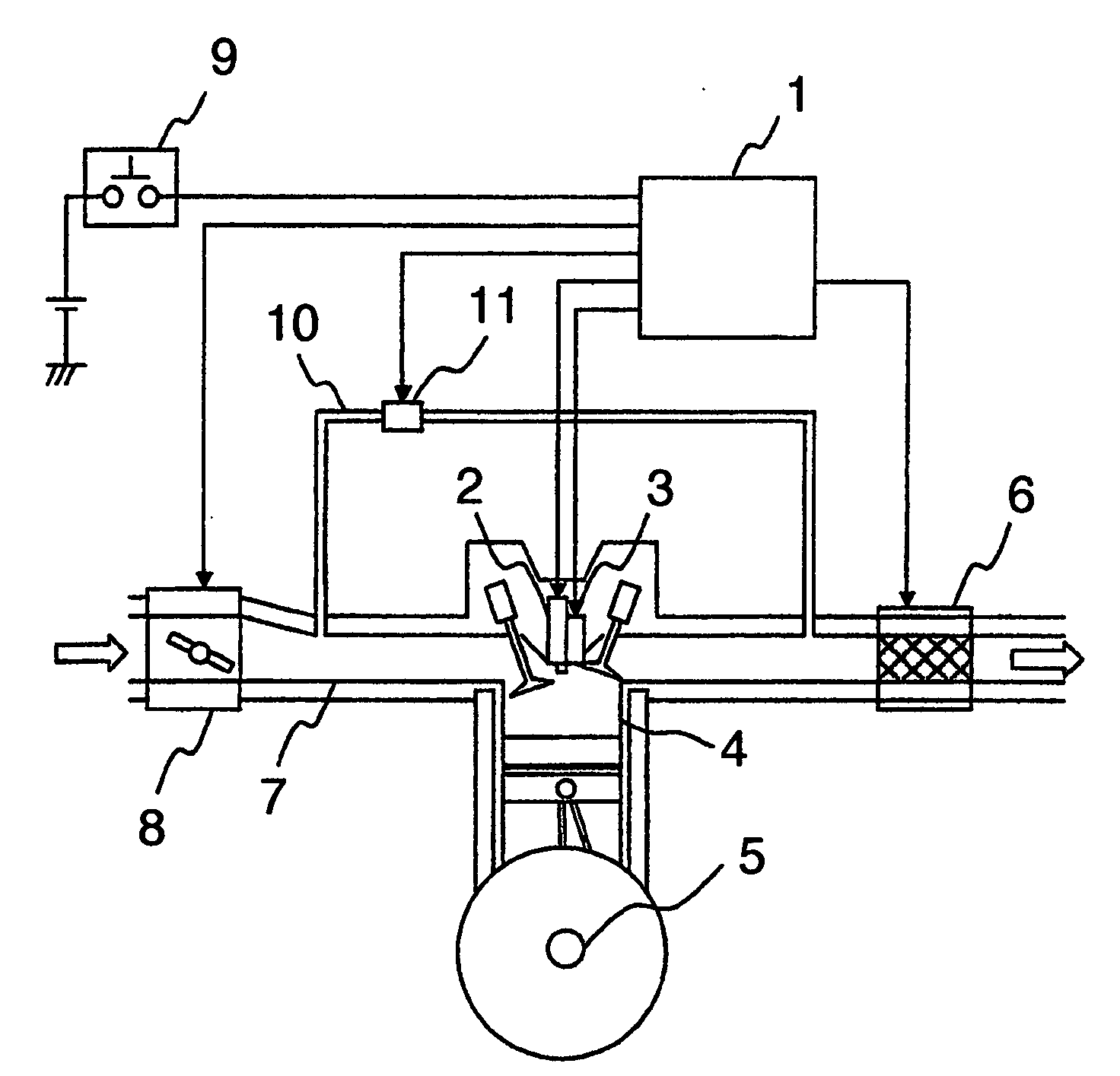
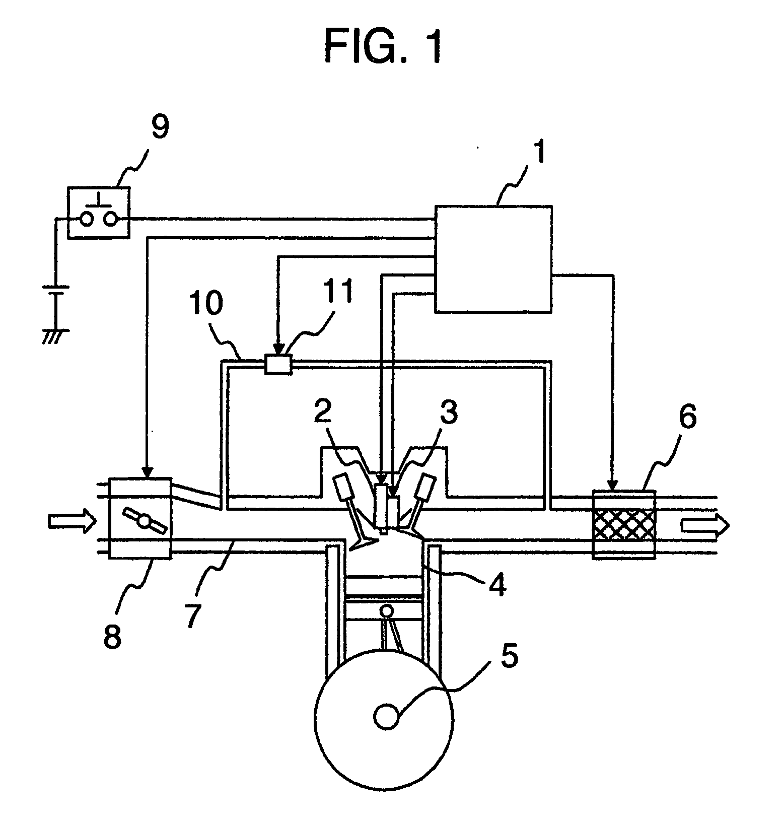
TECHNICAL FIELD[0001]The present invention relates to a throttle control device for an internal combustion engine and its control method.BACKGROUND ART[0002]A typical diesel engine operates, as shown in FIG. 1, by compressing air in a combustion chamber of the engine, injecting fuel into the air compressed and raised in temperature to cause combustion and explosion of the fuel and the air, and outputting the explosive power as the rotational motive power via the crank shaft. The exhaust gas contains a harmful substance, such as nitrogen oxides (NOx), and a precious metal catalyst is disposed in the exhaust pipe to reduce nitrogen oxides. Further, part of the exhaust gas from the combustion is recirculated to the intake pipe via an EGR valve and added to the intake air. This is for lowering the peak value of the combustion temperature and thus reducing the nitrogen oxides (NOx) in the exhaust gas by mixing the exhaust gas into the intake air.[0003]Unlike a gasoline engine which adjus...

Claims


Application Information

Patent Timeline
Patent Type & Authority Applications(United States)
IPC IPC(8): F02D9/08F02D11/10F02D41/00
CPCF02D9/02F02D9/1045F02D11/107F02D2200/0404F02D2009/0277F02D2011/102F02D41/221
Inventor JUMONJI, KENTARONAKANO, SHUUICHI
Owner HITACHI LTD
Learn More