Centrifugal compressor for use with low global warming potential (GWP) refrigerant

a centrifugal compressor and global warming potential technology, which is applied in the direction of machines/engines, liquid fuel engines, lighting and heating apparatus, etc., can solve the problems of limiting the operating range of centrifugal compressors, limiting the ability of 2d blades to be tailored to the particular operating conditions and refrigerants, and trade-offs in performance, so as to reduce the operating range, reduce the operating cost, and reduce the effect of losses

Active Publication Date: 2021-01-14
DAIKIN IND LTD
View PDF0 Cites 1 Cited by
  • Summary
  • Abstract
  • Description
  • Claims
  • Application Information

AI Technical Summary

Benefits of technology

[0008]Choke and surge are factors that limit the operating range in which a centrifugal compressor can be operated with adequate efficiency. There are several causes for the occurrence of choke and surge in a centrifugal compressor. Choke is a phenomenon that occurs when the centrifugal compressor is operated at or near the maximum mass flow rate that the centrifugal compressor is capable of. Meanwhile, surge is a phenomenon that occurs when the centrifugal compressor is operated at or near the minimum mass flow rate that the centrifugal compressor is capable of. It has been discovered that the operating range in which a centrifugal compressor can be operated without incurring choke or surge conditions can be widened by minimizing flow separation within the blade flow passage. By minimizing flow separation, the losses can be minimized and efficiency can be increased.

Problems solved by technology

Due to these definitions or “rules” imposed on the shape of the blades, there are limits to which a 2D blade can be tailored to the particular operating conditions and refrigerant type that will be used in the chiller system.
However, in many cases there are trade-offs in performance.
Choke and surge are factors that limit the operating range in which a centrifugal compressor can be operated with adequate efficiency.

Method used


Image

  • Centrifugal compressor for use with low global warming potential (GWP) refrigerant
  • Centrifugal compressor for use with low global warming potential (GWP) refrigerant
  • Centrifugal compressor for use with low global warming potential (GWP) refrigerant

Examples


Embodiment Construction

class="d_n">[0032]Select embodiments will now be explained with reference to the drawings. It will be apparent to those skilled in the art from this disclosure that the following descriptions of the embodiments are provided for illustration only and not for the purpose of limiting the invention as defined by the appended claims and their equivalents.

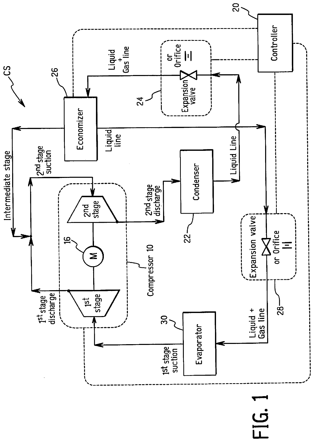
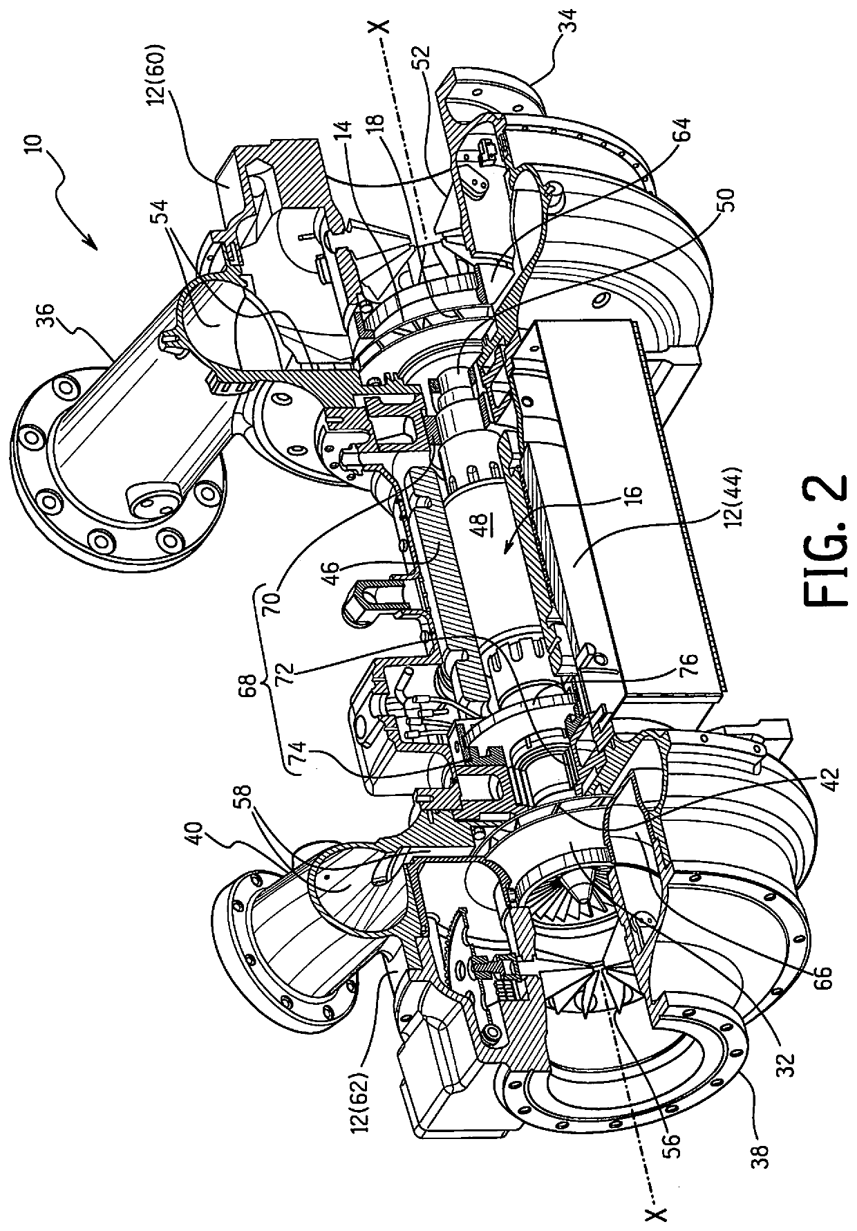
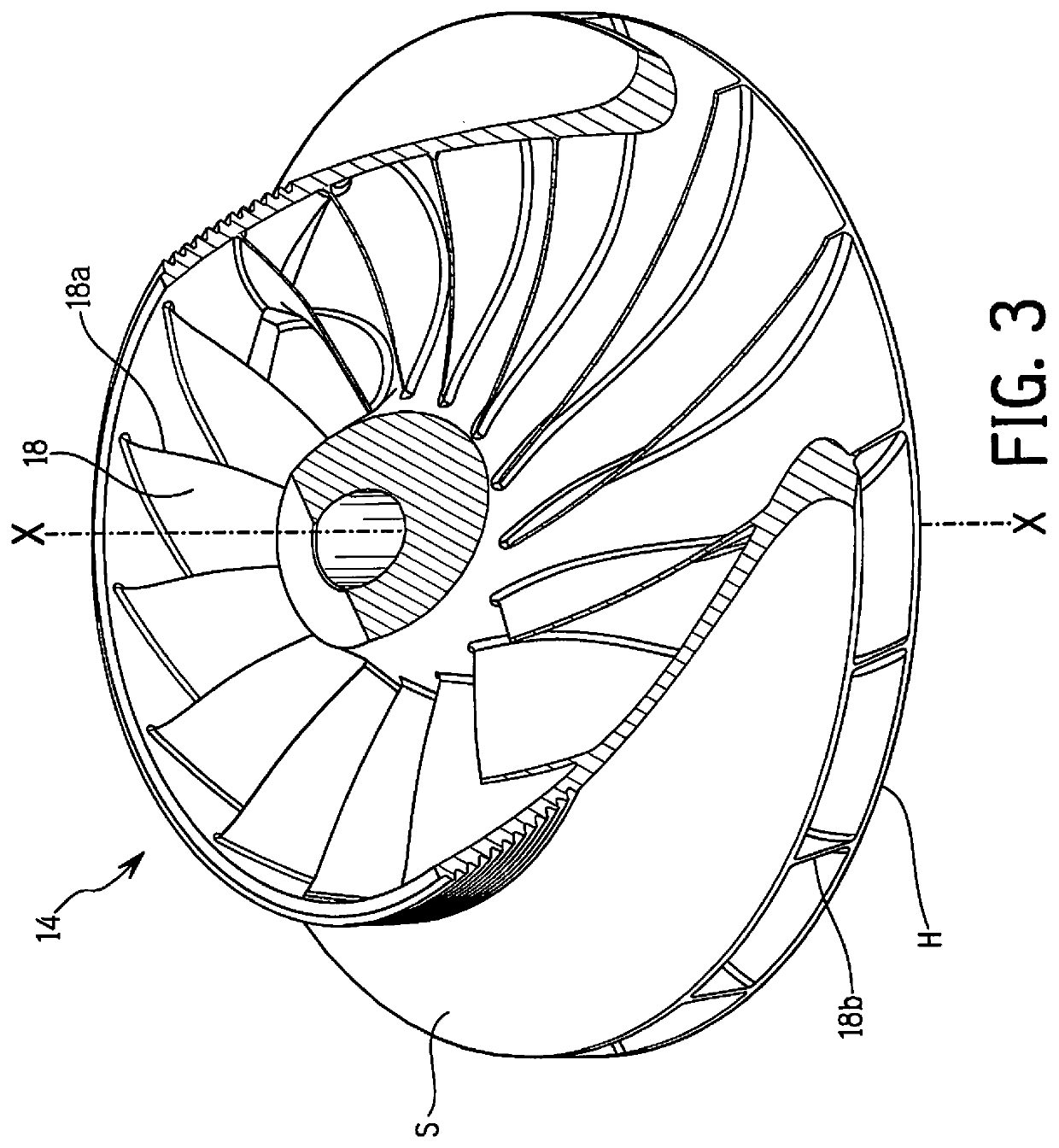
[0033]A centrifugal compressor 10 in accordance with the present invention is configured for use with a low global warming potential (GWP) refrigerant in loop refrigeration cycle (refrigeration circuit) and is particularly configured for use in an HVAC application. In the illustrated embodiment, the centrifugal compressor 10 is used in a chiller system CS as shown in FIG. 1. The centrifugal compressor 10 of this embodiment is a two stage compressor, and thus, the chiller system CS shown in FIG. 1 is a two stage chiller system. The centrifugal compressor 10 includes a casing 12, a first impeller 14 (first impeller), and a motor 16. As wil...


PUM


Abstract

A centrifugal compressor is configured to be used for compressing a low global warming potential (GWP) refrigerant. The centrifugal compressor comprises a casing, an impeller, and a motor for rotating the impeller. The impeller is equipped with blades having a fully nonlinear shape in a quasi-orthogonal cross-sectional view. A hub-side blade angle delta of each of the blades from a hub portion of the first impeller to a mid-span position of the blade varies along a streamwise direction such that the hub-side blade angle delta is largest at a position closer to a leading edge of the first blade than to a trailing edge of the first blade. The casing is configured such that the low global warming potential (GWP) refrigerant enters the impeller from the inlet portion along an axial direction of the impeller and exits the impeller to the outlet portion in a radial direction of the impeller.

Description

BACKGROUNDField of the Invention[0001]The present invention generally relates to a centrifugal compressor for use with a low global warming potential (GWP) refrigerant. More specifically, the present invention relates to a centrifugal compressor that has an impeller optimized for use with a low global warming potential (GWP refrigerant) in a chiller circuit.Background Information[0002]A refrigeration circuit for a chiller system typically includes a compressor to compress a refrigerant as part of a refrigeration cycle. The compressor is often a centrifugal compressor, also called a radial compressor or turbo compressor. A chiller system including a centrifugal compressor is sometimes called a turbo chiller. In a turbo chiller system, refrigerant is compressed in the centrifugal compressor and sent to a heat exchanger in which heat exchange occurs between the refrigerant and a heat exchange medium (liquid). This heat exchanger is referred to as a condenser because the refrigerant con...

Claims


Application Information

Patent Timeline
Patent Type & Authority Applications(United States)
IPC IPC(8): F04D17/12F04D29/28F25B31/02
CPCF04D17/122F25B31/026F04D29/286F04D29/284F04D29/30F05D2250/70
Inventor MASAKI, KENICHIDRAKE, MIDORIBUSCH, JASON
Owner DAIKIN IND LTD
Why Eureka
Try Eureka