Ms/ms mass spectrometer

a mass spectrometer and mass spectrometer technology, applied in mass spectrometers, instruments, separation processes, etc., can solve the problems of omission of analysis information in multi-component analysis, shortened and reduced detection sensitivity, etc., to achieve sufficient cid efficiency, short flight time, and the effect of reducing the time interval for repeating analysis tasks

Inactive Publication Date: 2010-04-29
SHIMADZU CORP
View PDF7 Cites 11 Cited by
  • Summary
  • Abstract
  • Description
  • Claims
  • Application Information

AI Technical Summary

Benefits of technology

[0018]In the MS / MS mass spectrometer according to the present invention, the length of the collision cell is less than approximately half compared to before, i.e. dramatically short. Therefore, the time period required for an ion to pass through the collision cell (to be more exact, the time period between the injection of a precursor ion and the exit of a product ion generated by the collision of the precursor ion) is fairly shortened. On the other hand, the length of the area required for a precursor ion to be sufficiently dissociated can be ensured inside the collision cell.
[0019]Therefore, the MS / MS mass spectrometer according to the present invention can achieve an unprecedentedly short flight time for an ion originating from an ion generated in an ion source, i.e. a product ion having a specific mass-to-charge ratio, to reach the detector, while maintaining a practically sufficient CID efficiency. Accordingly, for example, the mass scan rate in the second mass separator which is the subsequent stage may be increased and the time interval for a repeated analysis task may be shortened to densely perform an analysis. Consequently, the overlooking of a component can be reduced. In addition, since the ions which should be made to pass through the second mass separator reach the second mass separator without a large temporal variation, the ions' passage efficiency in the second mass separator is increased, which improves the detection sensitivity.
[0020]What is more, since it is also possible to prevent an undesired ion from remaining in the collision cell, the generation of a ghost peak on the mass spectrum is also avoided. Furthermore, since the ion's passage time can be shortened without forming a direct current electric field having a potential gradient in the ion's passage direction inside the collision cell, the configuration of the electrodes provided in the collision cell can be simplified and the voltage application circuit for the electrodes can also be simplified. Accordingly, it is advantageous in decreasing the apparatus' cost. In addition, the shortness of the collision cell is advantageous in downsizing the entire apparatus.
[0021]In the MS / MS mass spectrometer according to the present invention, the flow of the predetermined gas inside the collision cell may preferably be formed in the counter direction of the traveling direction of an ion.
[0022]With this configuration, it is possible to increase the energy that a precursor ion receives when the predetermined gas collides with the precursor ion injected into the collision cell. Hence, a high CID efficiency can be achieved with a relatively low gas pressure. Accordingly, the evacuation capacity of the vacuum pump for vacuum-evacuating the analysis chamber requires minimal enhancement, which is advantageous to the cost.

Problems solved by technology

Hence, if the ion's delay is significant as previously described, an ion which should normally pass through the third-stage quadrupole electrodes 15 might not be able to pass through it, which causes a degradation in the detection sensitivity.
Moreover, since it takes time for an ion to reach the detector 16, the time interval of the repeated analysis is required to be previously determined in view of such a situation, which might cause an omission of analysis information in a multi-component analysis.
However, even though such an acceleration is performed, in the conventional configuration, the time period for an ion to pass through the collision cell 14 is not negligible.
In the case where a direct current electric field having a potential gradient in the ion's passage direction is formed as previously described, the configuration of the electrodes themselves and that of the voltage application circuit are complicated compared to the case where a constant direct current electric field without a potential gradient is formed, which causes an increase in cost.

Method used


Image

  • Ms/ms mass spectrometer
  • Ms/ms mass spectrometer
  • Ms/ms mass spectrometer

Examples


first embodiment

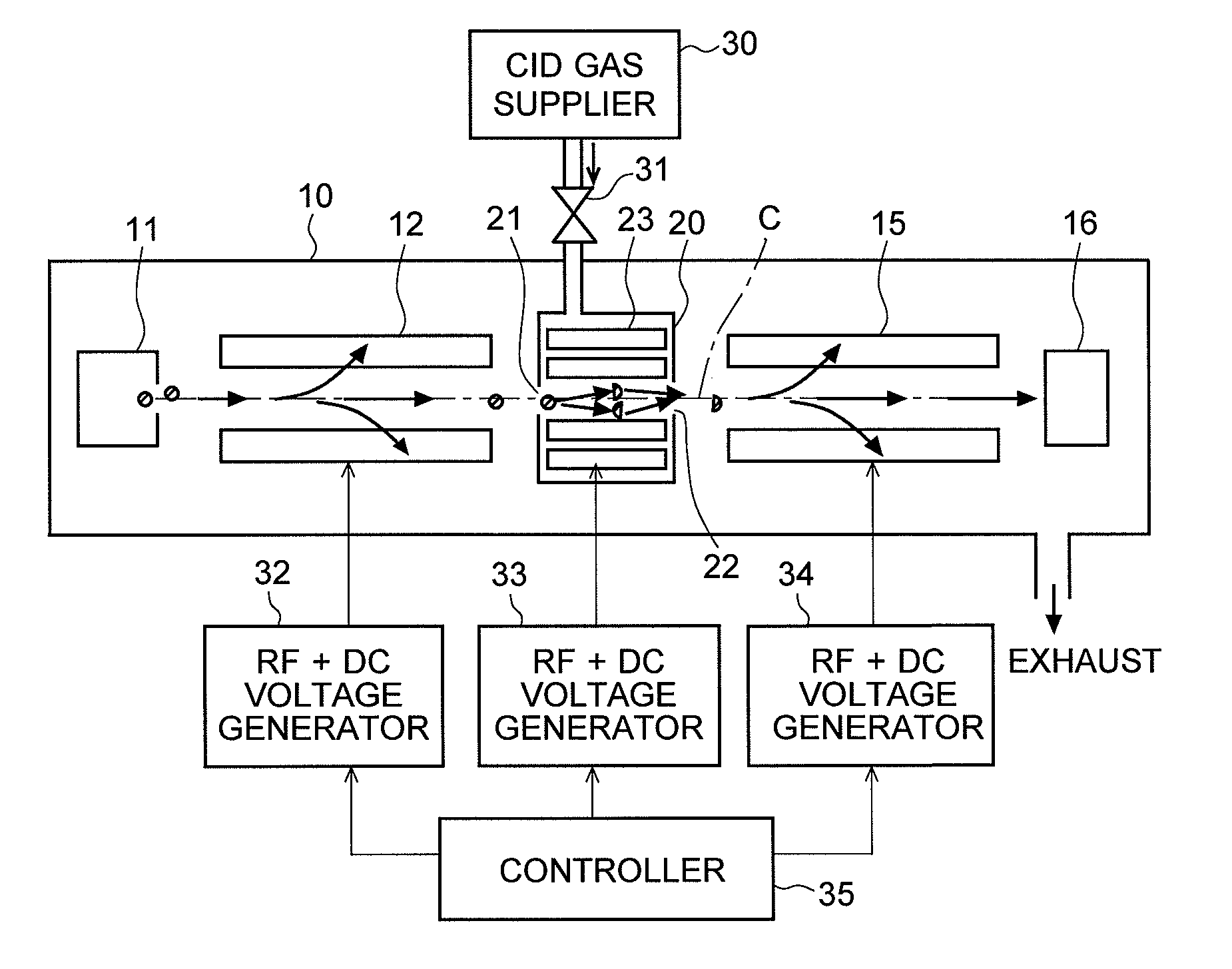
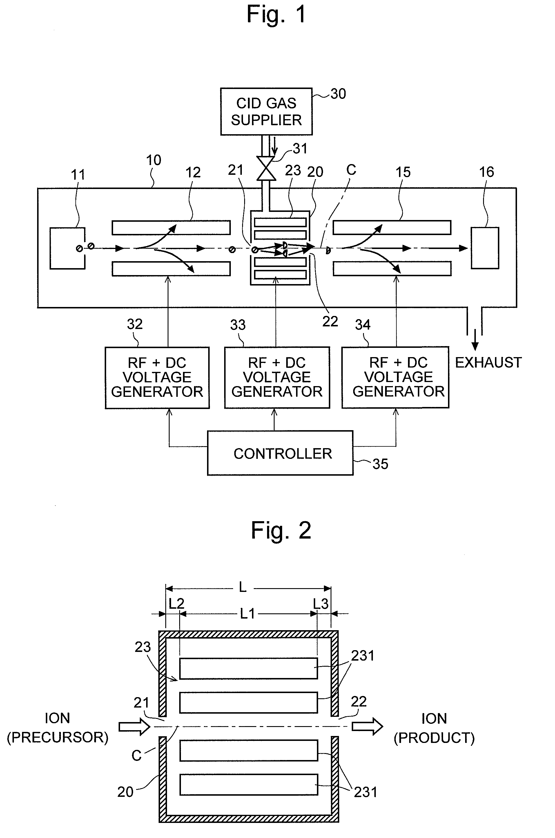
[0053]An MS / MS mass spectrometer which is an embodiment (or the first embodiment) of the present invention will be described with reference to the figures. FIG. 1 is an overall configuration diagram of the MS / MS mass spectrometer according to the first embodiment, and FIG. 2 is a detailed sectional view of a collision cell in the MS / MS mass spectrometer of the first embodiment. The same components as in the conventional configuration as illustrated in FIG. 15 are indicated with the same numerals and the detailed explanations are omitted.

[0054]In the MS / MS mass spectrometer of the first embodiment, as in a conventional configuration, a collision cell 20 is provided between the first-stage quadrupole electrodes 12 (which correspond to the first mass separator in the present invention) and the third-stage quadrupole electrodes 15 (which correspond to the second mass separator in the present invention) in order to generate a variety of product ions by dissociating a precursor ion. This ...

second embodiment

[0072]An MS / MS mass spectrometer which is another embodiment (or the second embodiment) of the present invention will be described with reference to the figures. The spectrometer in the second embodiment is almost the same as that in the first embodiment and only a portion of the collision cell's configuration is different. This configuration will be described with reference to FIG. 4.

[0073]As illustrated in FIG. 4, in the collision cell 20 in this embodiment, the gas ejection port 24a of the supply pipe 24 for supplying the CID gas is curved in the anterior direction. Accordingly, the CID gas spouted into the collision cell 20 from the gas ejection port 24a proceeds in the opposite direction of the ion's traveling direction, as indicated by the dashed arrows in the figure. Therefore, compared to the configuration of the first embodiment, ions introduced into the collision cell 20 collide with a CID gas having a larger energy, which enhances the efficiency of the dissociation. Hence...

modification example

[0074]The configuration of the electrode for forming a radio-frequency electric field disposed in the collision cell 20 is not limited to the octapole electrodes as in the aforementioned embodiments, but can be modified in a variety of ways including various types of conventionally known configurations. Concretely speaking, multipole electrodes may be used such as quadrupole electrodes and hexapole electrodes, other than octapole electrodes. With such a simple multipole configuration, a constant direct current electric field is formed in the direction of the ion optical axis C. Since the collision cell is short, it is possible to make an ion pass through the collision cell in a short period of time even with a constant direct current electric field.

[0075]Electrodes having a different configuration as illustrated in FIGS. 5 through 12 may be used. With each of these modifications, a direct current having a potential gradient in the direction along the ion optical axis C is formed and...


PUM


Abstract

The length of the collision cell (20) in the direction along the ion optical axis (C) is set to be within the range between 40 and 80 mm, and typically 51 mm, which is remarkably shorter than before. The CID gas is supplied so that it flows in the direction opposite to the ion's traveling direction. Since the energy that an ion receives in colliding with a CID gas increases, it is possible to practically and sufficiently ensure the CID efficiency even though the collision cell (20) is short. In addition, since the passage distance for an ion is short, the passage time is shortened. Accordingly, it is possible to avoid the degradation in the detection sensitivity and the generation of a ghost peak due to the delay of the ion.

Description

TECHNICAL FIELD[0001]The present invention relates to an MS / MS mass spectrometer for dissociating an ion having a specific mass-to-charge ratio by a collision-induced dissociation (CID) and mass analyzing the product ion (or fragment ion) generated by this process.BACKGROUND ART[0002]A well-known mass-analyzing method for identifying a substance having a large molecular weight and for analyzing its structure is an MS / MS analysis (or tandem analysis). FIG. 15 is a schematic configuration diagram of a general MS / MS mass spectrometer disclosed in Patent Documents 1 through 3 or other documents.[0003]In this MS / MS mass spectrometer, three-stage quadrupole electrodes 12, 13, and 15 each composed of four rod electrodes are provided, inside the analysis chamber 10 which is vacuum-evacuated, between an ion source 11 for ionizing a sample to be analyzed and a detector 16 for detecting an ion and providing a detection signal in accordance with the amount of ions. A voltage ±(U1+V1·cos ωt) is ...

Claims


Application Information

Patent Timeline
Patent Type & Authority Applications(United States)
IPC IPC(8): H01J49/26
CPCG01N27/62H01J49/062H01J49/005
Inventor OKUMURA, DAISUKEITOI, HIROTOMUKAIBATAKE, KAZUO
Owner SHIMADZU CORP
Why Eureka
Try Eureka