[0024] Photoselective vaporization of tissue, such as the prostate for treatment of BPH, is based upon applying a
high intensity radiation to prostate tissue using a radiation that is highly absorptive in the tissue, while being absorbed only to a negligible degree by water or other irrigant during the operation, at power densities such that the majority of the energy is converted to vaporization of the tissue without significant residual coagulation of adjacent tissue. Unlike prior art techniques for treatment of BPH, the procedure may be conducted under
local anesthesia, and patients are usually able to go home a couple of hours after the procedure. The procedure results in fewer side effects than prior art techniques, including
lower incidence of
dysuria and hemouria. Patients may be treated without requiring post-operative catherization of the
urethra.
[0026] Operation of the
solid-state laser in a “
macro-pulsed” mode is more efficient in inducing rapid tissue vaporization than a
CW laser of the same average power. This is in part because the
macro-pulsing is more efficient in inducing “
char” formation, a mild
carbonization in which the tissue typically darkens slightly but does not necessarily turn completely black. Although
char formation is not essential to efficient rapid vaporization it is helpful because the darkened tissue is better at absorbing light. The
macro-
pulsed laser is also more efficient and has higher beam quality, with M2 values typically less than 144, than a
continuous wave laser with same average output power.
[0030] It has been recognized that as more and more laser energy is consumed by vaporization of the tissue, the amount of laser energy leading to residual tissue coagulation gets smaller, i.e. the amount of residual coagulation drops, and the side effects attendant to the residual injury caused by the
surgery drop dramatically. Thus, the extent of the zone of
thermal damage characterized by tissue coagulation left after the procedure gets smaller with increasing volumetric
power density, while the rate of vaporization increases. Substantial and surprising improvement in results is achieved. It has been recognized that increasing the volumetric
power density absorbed in the tissue to be vaporized, has the result of decreasing the extent of residual injury of the surrounding tissue. This recognition leads to the use of
higher power laser systems, with greater levels of
irradiance at the treatment area on the tissue, while achieving the lower levels of adverse side effects and a quicker operation times.
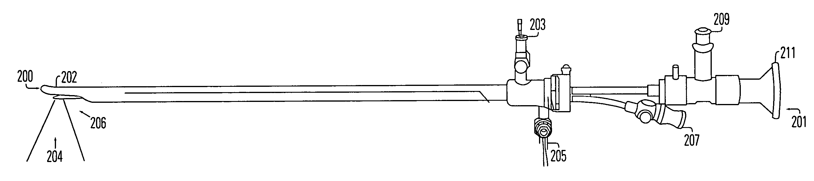
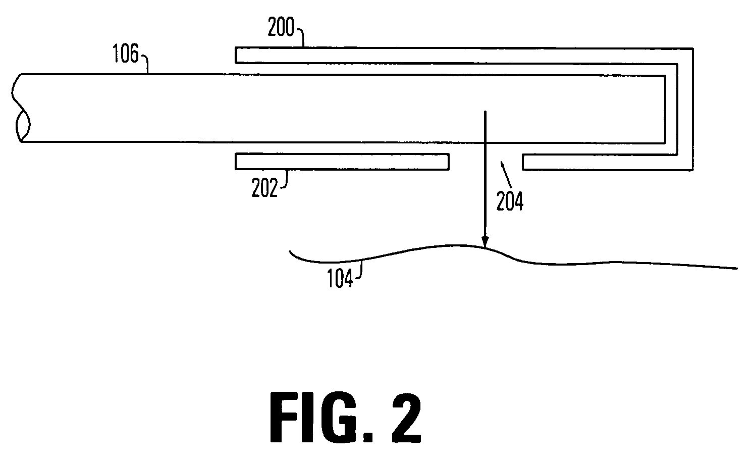
[0033] Accordingly, in one embodiment, the second
harmonic output of the
neodymium dope
solid-state laser is applied using a side firing tip on the
optical fiber. The side firing tip, which causes a diverging beam to be directed out of the
optical fiber, is placed close to the tissue, within about 1 mm from the side of the side firing tip. Close placement increases the
irradiance delivered to the treatment area so that higher irradiance is available with
solid-state lasers generating a 60 to 80 watts average output power.
[0034] According to the present invention, the efficiency of the vaporization and the reduction of injury to residual tissue are sufficient that the procedure may be carried out while applying only
local anesthetic during the delivery of laser energy, and throughout the procedure. For example, a procedure according to the present invention includes applying intraurethral topical
anesthesia such as
lidocaine, either a periprostatic block or a perirectal block, oral and / or intravenous drugs such as
Fentanyl or Demerol, chilled irrigant, and irrigant containing
anesthesia.
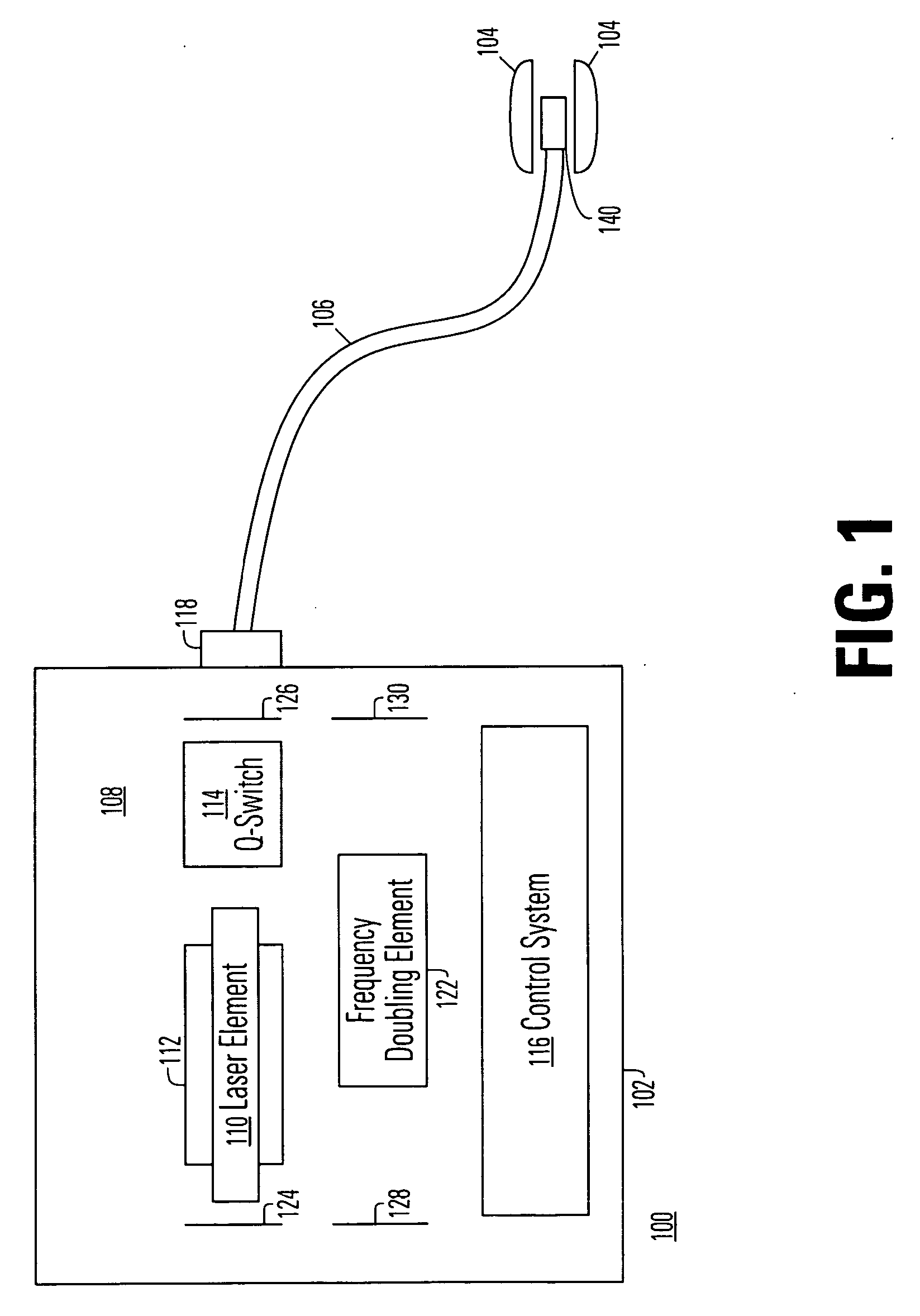
[0035] Furthermore, embodiments of the invention include the delivery of the laser energy using a Q-switched, solid-state laser which produces micro-pulses in combination with applying pump power to the laser medium in a sequence a pulses so that output radiation is produced in macro-pulses having a peak power of greater than 200 watts, and more preferably about 240 watts or greater. The peak irradiance in the treatment area during the pulses is thereby substantially increased, and preferably greater than 50 kilowatts / cm2, and as much as 90 kilowatts / cm2 in some embodiments of the invention.

