Method and system for item marking and identification

a technology of applied in the field of method and system for item marking and identification, can solve the problems of many such cameras on the market producing blurred images, images extracted by mobile device cameras are not always of a quality sufficient for bar codes, and bar codes are typically not aesthetically pleasing to human observers, so as to facilitate and speed up user's work, limit the range of operations, and limit computational capacity

Inactive Publication Date: 2021-02-18
HOOK JAROSLAV
View PDF0 Cites 0 Cited by
  • Summary
  • Abstract
  • Description
  • Claims
  • Application Information

AI Technical Summary

Benefits of technology

[0066]2) Due to use of angle invariant spectral-polarization-temporal characteristics of the Fluorescent Code, their respective readers can operate at very blunt incidence angles (as little as 10 degrees to the surface plane) unlike bar codes readers which oftentimes require angles for their operations close to perpendicular (at least 60 degrees). This capacity facilitates and speeds up user's work.
[0067]3) Due to use of temporal dimension in spectral-polarization-temporal characteristics of the Fluorescent Code (FC), their respective Fluorescent Code Readers (FCR) can operate at larger distances than bar codes readers which require a certain spatial resolution thus limiting the range of the operations.
[0068]4) Due to the use of temporal spectral characteristics of the FMs, their respective FCRs can operate at busy and noisy scenes inherently better than bar codes readers. The later may have limited computational capacity and have to execute computationally intensive image processing algorithms to identify the said bar codes among such a busy scene.
[0069]6) Due to the use of temporal spectral characteristics of the FMs, their respective FMRs can operate at busy and noisy scenes inherently better than bar codes readers. The later may have limited computational capacity and have to execute computationally intensive image processing algorithms to identify the said bar codes among such a busy scene.

Problems solved by technology

In addition, the bar codes are typically not aesthetically pleasing to a human observer.
Nevertheless, the images extracted by mobile device cameras are not always of a quality sufficient for the bar code.
Many such cameras on the market have produce blurred images.
Very few mobile phones have a flash which increases the problem of the motion blur and sensor noise.
All of the above factors, including low image quality, make bar code reading problematic under in certain circumstances.
Moreover, all available camera-based bar code readers have poor performance under difficult light conditions, or at larger distances.

Method used


Image

  • Method and system for item marking and identification
  • Method and system for item marking and identification
  • Method and system for item marking and identification

Examples


first embodiment

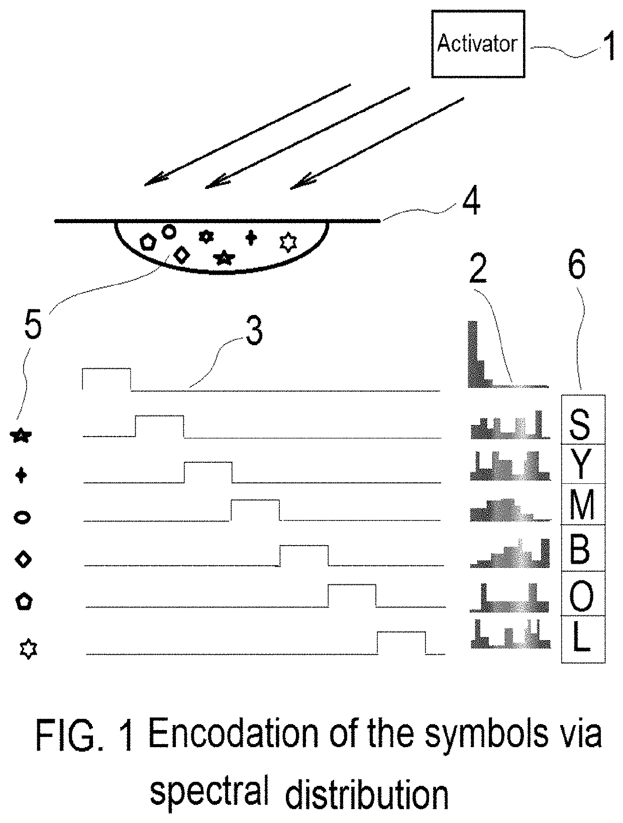
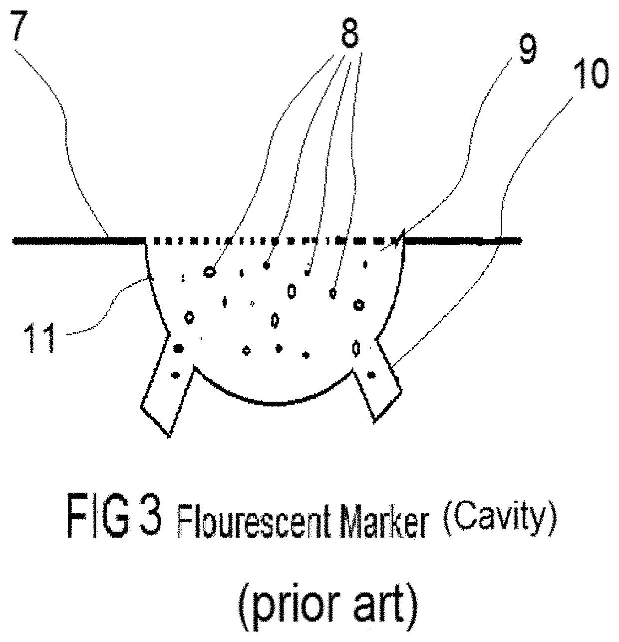
[0075]Understanding of the said FC will be further enhanced with the aid of FIG. 1,2,3. The item's surface contains a Cavity (11) of an arbitrary shape also comprises at least two Outlets (10). The said Cavity (11) is located below the plane of the item's surface. The said Cavity (11) is filled in with the Transparent Solid Medium (TSM) (9). The said outlets (10) are shaped in order to keep the TSM firmly inside the said Cavity. The maximum size at the cross section of the said Cavity (11) is kept 5 mm or at most ¼ of the cross-section of the surrounding item's area, whichever is smaller. In a preferred embodiment shown on FIG. 3 the said TSM top's surface is aligned with the same of the said item. Furthermore the said TSM contains a collection of PDFE (5,8,14 of FIG. 3, FIG. 4 respectively). Each particle in the said collection is chosen in such a way that they all have the non-overlapping afterglow times and the respective spectral / polarization characteristics encode a symbol from...

second embodiment

[0077]In its second embodiment the said FC has a flat shape shown on FIG. 4, wherein the top surface of TSM does not elevate above the surface (12) of the said item more than 2 mm. It comprises a layer of TSM (13) with enclosures at least one fluorescent / phosphorescent Particle (FPP) wherein FPP forms PDFE (5, 8, 14). The said TSM (13) is attached to the item's surface by an adhesive material (15). Similarly each particle encodes exactly one symbol.

[0078]The said PDFE (5,8,14) comprises at least one individual Fluorescent / Phosphorescent Particle-oentity (FPP) of a maximum size of 0.1 mm. The critical physical properties of the said FPP are polarization degree, after emission spectrum, the associated time delay. The said after emission spectrum average of each said particle (FPP) is within 300 through 1000 nm with width of the spectral band of no more than 250 nanometers. The absorption spectrum is within he said spectral band minus 100 nm with the width no more than 200 nm. The asso...


PUM


Abstract

A method and system for item marking and identification, representing an alternative to bar code reading, based on a a time-varying post emission of a plurality of fluorescent/phosphorescent items embedded into a marker embodiments of the present invention thus providing optical markers for information exchange. In a typical embodiment, information to be transmitted is divided into packets, whereas each packet represents a unique wavelength spectrum or signature. The said emission signature is generated in packets as a response to an activation signal is then analyzed sequentially. The varying spectral content of each said packet encodes a symbol, while symbol's position is encoded with the timing of the after-emission packet.

Description

REFERENCES CITED[0001]The below references are incorporated by the reference herein in their entirety and relied upon.U.S. PATENT DOCUMENTSUS 8,249,350B2Aug 21, 2012Svyatoslav Voloshynovskyy et al.US 8,542,871B2Sep 24, 2013Svyatoslav Voloshynovskyy et al.US 8,705,873B2Apr 22, 2014Svyatoslav Voloshynovskyy et al.US 8,034,398 B2, 2011AJun 6, 2002Gary Ross,US 8,287,993 B2, 2012AJun 6, 2002Xio-Dong, Fremont, CAUS 2,612,994 B2, 1952AOctober 1952Norman J. Woodlandet al., Philadelphia, Pa.RELATED US PATENT APPLICATIONS[0002]Application U.S. Ser. No. 15 / 847,912 2017 Jaroslav Hook[0003]Application U.S. Ser. No. 15 / 924,269 2018 Jaroslav HookOTHER PUBLICATIONS[0004][1] Peiwei Gong, Jinqing Wang, Weiming Sun et al. Tunable photoluminescence and spectrum split from fluorinated to hydroxylated graphene [0005][2] Erin Hendrick, Margaret Frey, Erik Herz, Ulrich Wiesner, Cellulose Acetate Fibers with Fluorescing Nanoparticles for Anti-counterfeiting and pH-sensing Applications, Journal of Engineered...

Claims


Application Information

Patent Timeline
Patent Type & Authority Applications(United States)
IPC IPC(8): G06K19/06G06K7/12
CPCG06K19/0614G06K7/12G06K19/06112G06K19/06028
Inventor HOOK, JAROSLAV
Owner HOOK JAROSLAV
Why Eureka
Try Eureka