
Automated meter reading power line communication system and method

a technology of automatic meter reading and power line communication, applied in the field of data communication, can solve the problems of limiting the strength of data signals that can be injected onto power lines, affecting the economic feasibility of communication with the utility, and not being able to provide high-speed data communication

Inactive Publication Date: 2007-07-24
CURRENT TECH
View PDF209 Cites 51 Cited by
  • Summary
  • Abstract
  • Description
  • Claims
  • Application Information

AI Technical Summary

Benefits of technology

"The present invention is an automated system for measuring and transmitting utility usage data through a power line. The system includes a device that measures the customer's usage and stores it in memory, which is then transmitted wirelessly to a second device connected to the power line. The technical effect is that this system allows for more efficient and accurate monitoring of utility usage, reducing the need for manual readings and improving overall efficiency."

Problems solved by technology

Power lines are not designed to provide high speed data communications and can be very susceptible to interference.
Additionally, federal regulations limit the amount of radiated energy of a power line communication system, which therefore limits the strength of the data signal that can be injected onto power lines (especially overhead power lines).
Consequently, due to the attenuation of power lines, communications signals typically will travel only a relatively short distance on power lines.
In the past, utilities typically have sent personnel to manually read and record the meter data, which can be expensive.
However, until now, there has been no economically feasible means of communicating the data to the utility.
This fact, along with the cost of replacing old meters in a large geographical area, have hindered wide scale adoption of automated meter reading.

Method used


Image

  • Automated meter reading power line communication system and method
  • Automated meter reading power line communication system and method
  • Automated meter reading power line communication system and method

Examples


Embodiment Construction

[0014]In the following description, for purposes of explanation and not limitation, specific details are set forth, such as particular networks, communication systems, computers, terminals, devices, components, techniques, PLCS, data and network protocols, software products and systems, operating systems, development interfaces, hardware, etc. in order to provide a thorough understanding of the present invention.

[0015]However, it will be apparent to one skilled in the art that the present invention may be practiced in other embodiments that depart from these specific details. Detailed descriptions of well-known networks, communication systems, computers, PLCS, terminals, devices, components, techniques, data and network protocols, software products and systems, operating systems, development interfaces, and hardware are omitted so as not to obscure the description of the present invention.

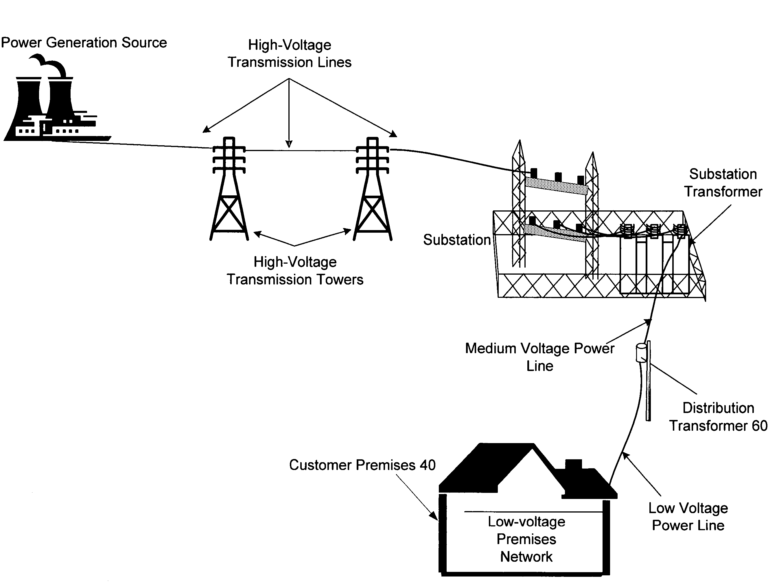
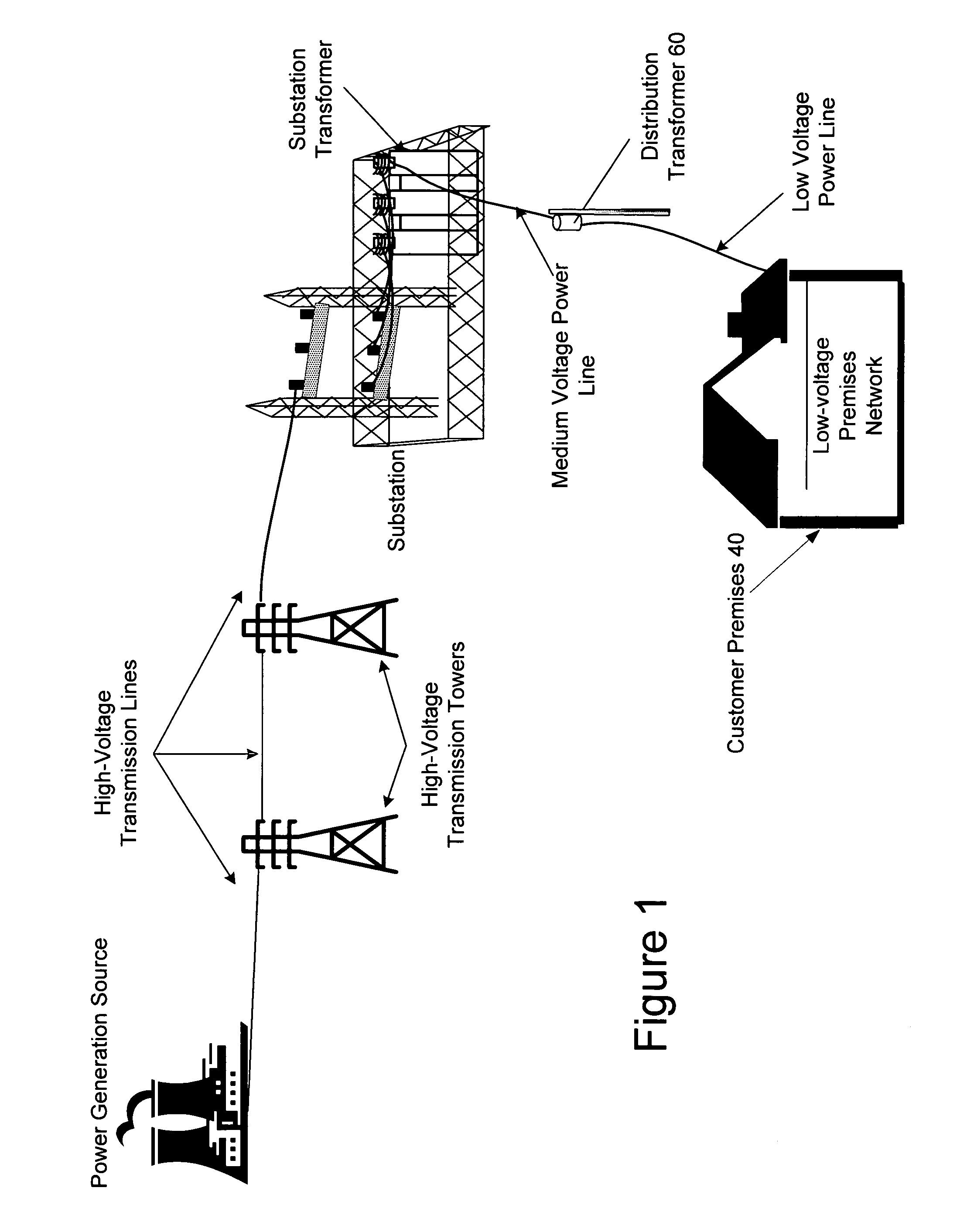
[0016]As shown in FIG. 1, power distribution systems typically include components for power gen...


PUM


Abstract

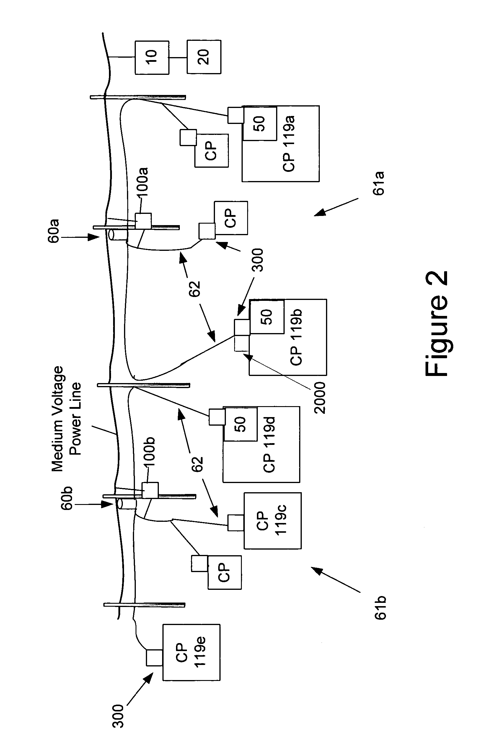
An automated meter reading power line communications system is provided, which may include measuring the utility usage of a first customer premises to provide first utility usage data, storing the first utility usage data in memory of a first device, wirelessly transmitting the first utility usage data from the first device, receiving the wirelessly transmitted first utility usage data at a second device coupled to a medium voltage power line, and transmitting the first utility usage data over the medium voltage power line.

Description

CROSS REFERENCE TO RELATED APPLICATIONS[0001]This application is a continuation-in-part of and claims priority to U.S. patent application Ser. No. 10 / 075,332, filed Feb. 14, 2002, which claims priority to U.S. Provisional Patent Application Ser. Nos. 60 / 268,519 and 60 / 268,578, (both filed Feb. 14, 2001); and this application is a continuation-in-part of and claims priority to U.S. patent application Ser. No. 11 / 134,377 filed May 23, 2005, which is a continuation of U.S. patent application Ser. No. 09 / 835,532, now U.S. Pat. No. 6,958,680, filed Apr. 16, 2001, which claims priority to U.S. Provisional Patent Application Ser. No. 60 / 197,615 filed Apr. 14, 2000, all of which are hereby incorporated herein by reference in their entirety for all purposes.FIELD OF THE INVENTION[0002]The present invention generally relates to data communications over a power distribution system and more particularly, to a power line communications system for wirelessly communicating utility meter data and o...

Claims


Application Information

Patent Timeline
Patent Type & Authority Patents(United States)
IPC IPC(8): G08B1/08
CPCG01D4/004H04B3/544H04L45/00H04Q9/00H04B2203/5433H04B2203/5441Y02B90/242Y04S20/322H04Q2209/25H04Q2209/60Y02B90/20Y04S20/30
Inventor BERKMAN, WILLIAM H.KLINE, PAUL A.
Owner CURRENT TECH
Learn More