Vehicle periphery monitor

Active Publication Date: 2007-07-24
TOYOTA JIDOSHA KK +1
View PDF17 Cites 225 Cited by
  • Summary
  • Abstract
  • Description
  • Claims
  • Application Information

AI Technical Summary

Benefits of technology

[0009]It is an object of the invention to construct a vehicle periphery monitor capable of informing a driver of a situation s

Problems solved by technology

Hence, in an attempt to suitably check safety or the like by looking at the indicator display, the driver is confronted with an increase in operational burden.
Hence, the driver is confronted with an excessive increase in operational burden.
According to this method, the photo images displayed by the indicator disp

Method used


Image

  • Vehicle periphery monitor
  • Vehicle periphery monitor
  • Vehicle periphery monitor

Examples


first embodiment

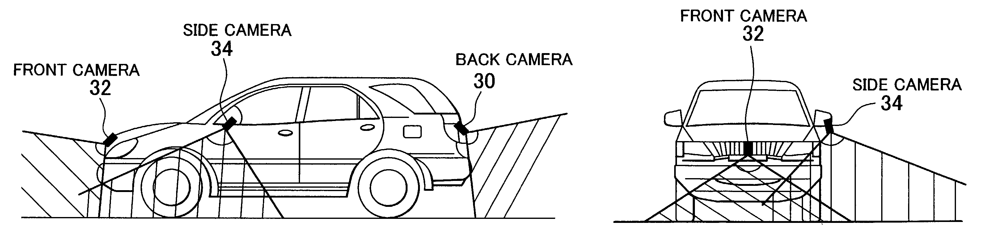
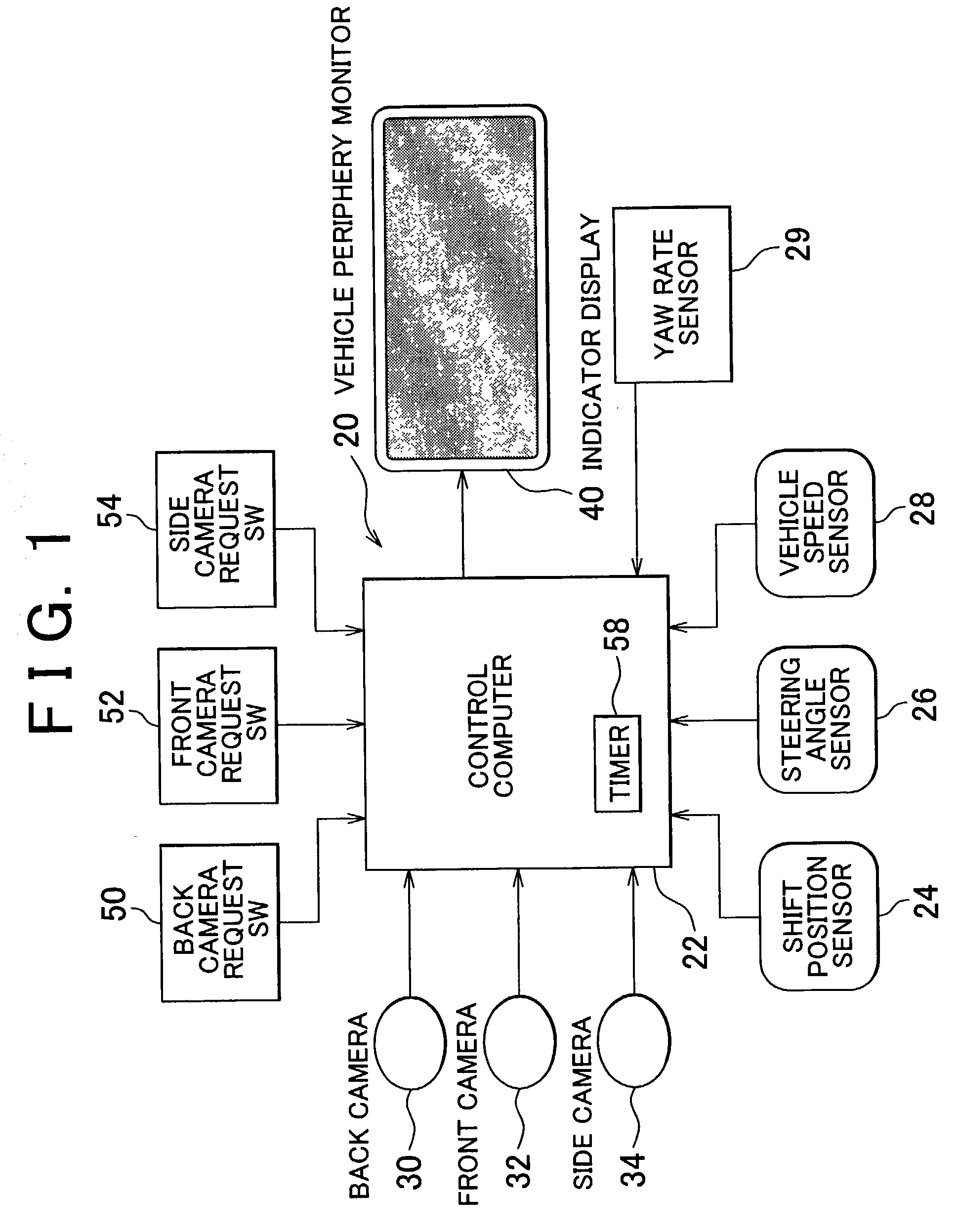
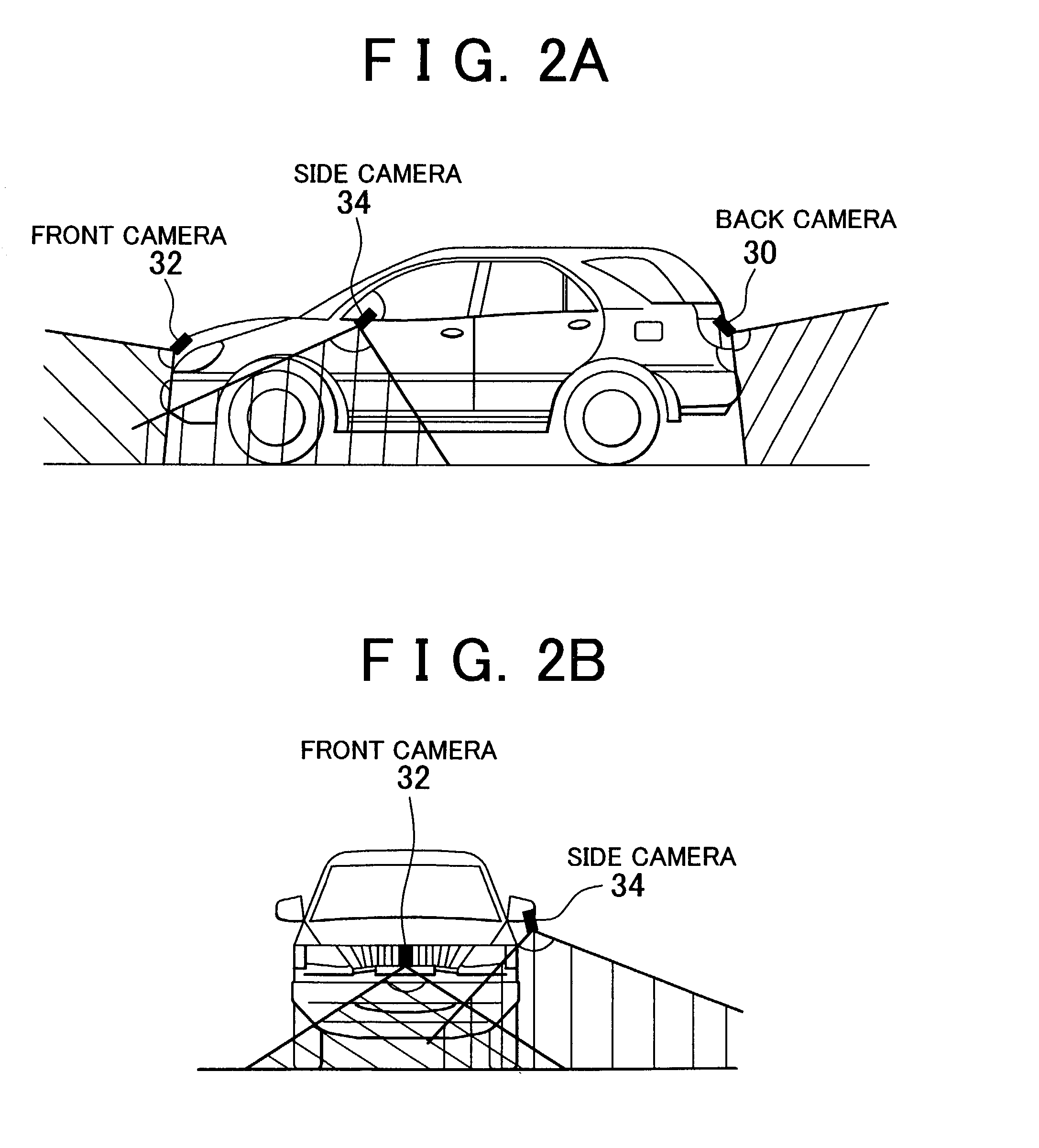
[0043]FIG. 1 shows a system configuration of a vehicle periphery monitor 20 in accordance with the invention. In this embodiment, a vehicle equipped with the vehicle periphery monitor 20 has front wheels as turnable wheels that are turned in accordance with a steering operation performed by the driver and rear wheels as non-turnable wheels. The vehicle periphery monitor 20 has a monitor-purpose electronic control computer (hereinafter referred to simply as “a computer”) 22. The computer 22 controls the vehicle periphery monitor 20.

[0044]A shift position sensor 24, a steering angle sensor26, and a vehicle speed sensor 28 are connected to the computer 22. The shift position sensor 24 outputs a signal corresponding to a position of a gearshift lever operated by the driver. The steering angle sensor 26 outputs a signal corresponding to a steering angle δ of a steering wheel operated by the driver. The vehicle speed sensor 28 generates a pulse signal at intervals of a period correspondin...

second embodiment

[0085]Next, the invention will be described with reference to FIG. 6 as well as FIGS. 1 and 2.

[0086]In the aforementioned first embodiment, the photo images filmed by the cameras 30 to 34 are displayed by the indicator display 40, in principle, through the operation of the request switches 50 to 54 performed by the driver. On the other hand, in the second embodiment, while the vehicle is running, photo images filmed by the cameras 30 to 34 are selectively displayed by the indicator display 40 in accordance with a running state of the vehicle, without requiring the driver to perform any operation. In the second embodiment, components identical to those of the aforementioned construction shown in FIG. 1 are denoted by the same reference numerals and will not be described again below.

[0087]If the steering angle δ is large under the situation in which the vehicle travels forwards, the turning radius of the vehicle is small. The lateral photo image filmed by the side camera 34 often cove...

third embodiment

[0104]Next, the invention will be described with reference to FIG. 7 as well as FIGS. 1 and 2.

[0105]When starting the vehicle from a stopped state, the driver first has to confirm, just before takeoff, a situation of an area toward which the vehicle is to travel. Thus, the third embodiment is designed to help the driver check safety by causing the indicator display 40 to display a peripheral situation of the vehicle as a photo image in the case where the vehicle is ready for takeoff, without requiring the driver to perform any operation. In the third embodiment, components identical to those of the aforementioned construction shown in FIG. 1 are denoted by the same reference numerals and will not be described again below.

[0106]During takeoff of the vehicle as well, as has been described above in the second embodiment, it is appropriate, from the standpoint of informing the driver of a situation to which the driver has to pay attention in the traveling direction of the vehicle, that ...


PUM


Abstract

A front camera for filming an area stretching forwards is disposed in a front portion of a vehicle. A side camera for filming an area stretching laterally and diagonally forwards is disposed in a lateral-left portion of the vehicle. An indicator display that can be visually recognized by a driver is disposed in a compartment of the vehicle. An amount of change in the direction of the vehicle, that is, a deflection angle of the vehicle is detected on the basis of a vehicle speed and a steering angle of a steering wheel, which have been detected by means of various sensors. After the indicator display has started displaying a lateral photo image filmed by the side camera, the photo image displayed by the indicator display is shifted from the lateral photo image filmed by the side camera to a front photo image filmed by the front camera if the deflection angle has reached a predetermined angle.

Description

INCORPORATION BY REFERENCE[0001]The disclosure of Japanese Patent Application No. 2001-346603 filed on Nov. 12, 2001, including the specification, drawings, and abstract is incorporated herein by reference in its entirety.BACKGROUND OF THE INVENTION[0002]1. Field of the Invention[0003]The invention relates to a vehicle periphery monitor for monitoring the periphery of a vehicle.[0004]2. Description of the Related Art[0005]In general, as disclosed in Japanese Patent Laid-Open Application No. 2000-172996, there is a vehicle periphery monitor having an indicator display for selectively or synthetically displaying a plurality of photo images representing different areas surrounding a vehicle. This monitor is provided with a plurality of cameras disposed in front and rear portions of the vehicle, and can capture a plurality of photo images representing different areas surrounding the vehicle. This monitor has a switch that can be operated by the driver.[0006]In the aforementioned vehicle...

Claims


Application Information

Patent Timeline
IPC IPC(8): H04N7/18G08G1/017H04N5/222B60R21/00B60R1/00B60R11/02
CPCB60R1/00H04N7/18B60R2300/105B60R2300/302B60R2300/70
Inventor TAKAGI, MAKOTOKATSUNO, TOSHIYASUKONNO, KAZUSHIKAKINAMI, TOSHIAKI
Owner TOYOTA JIDOSHA KK
Why Eureka
Try Eureka