
Article locating and tracking system

a tracking system and tracking technology, applied in the field of monitoring activities, can solve the problems of caregivers (e.g., nurses) and patient ratios continuing to decline, work under high pressure, and high stress, and achieve the effects of high stress, long hours, and high pressur

Active Publication Date: 2007-07-24
HILL ROM SERVICES
View PDF158 Cites 185 Cited by
  • Summary
  • Abstract
  • Description
  • Claims
  • Application Information

AI Technical Summary

Benefits of technology

[0004]As alluded to above, caregiver (e.g., nurse) to patient ratios continue to decline due to increasing economic pressures. Many healthcare facilities are exploring ways to reduce the non-value added activities of the caregivers (e.g., nurses) in order to maintain quality care while reducing the number of caregivers per patient. Computers hold promise for aiding the caregivers to work more efficiently by eliminating activities previously performed by caregivers and / or reducing the amount of time associated with the performance of caregiver activities. However, conventional uses of computers in the above locating and identification systems only supply the caregivers with information and at the most alarms indicating possible adverse events. Computer systems need to become aware of activities within the hospital environment if they are to reduce employee workload. To enable this evolution in computing technology, Activity Based Tracking (“ABT”) is needed. ABT is, in a general sense, the real-time connectivity of information (i.e. location, time, and device activity, etc.) to detect the occurrence of a specific activity for which a known response is acted upon by an automated system.
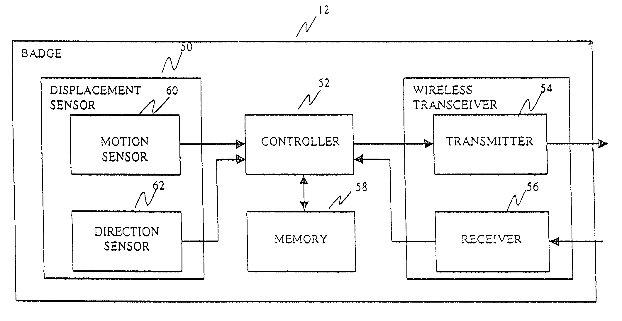
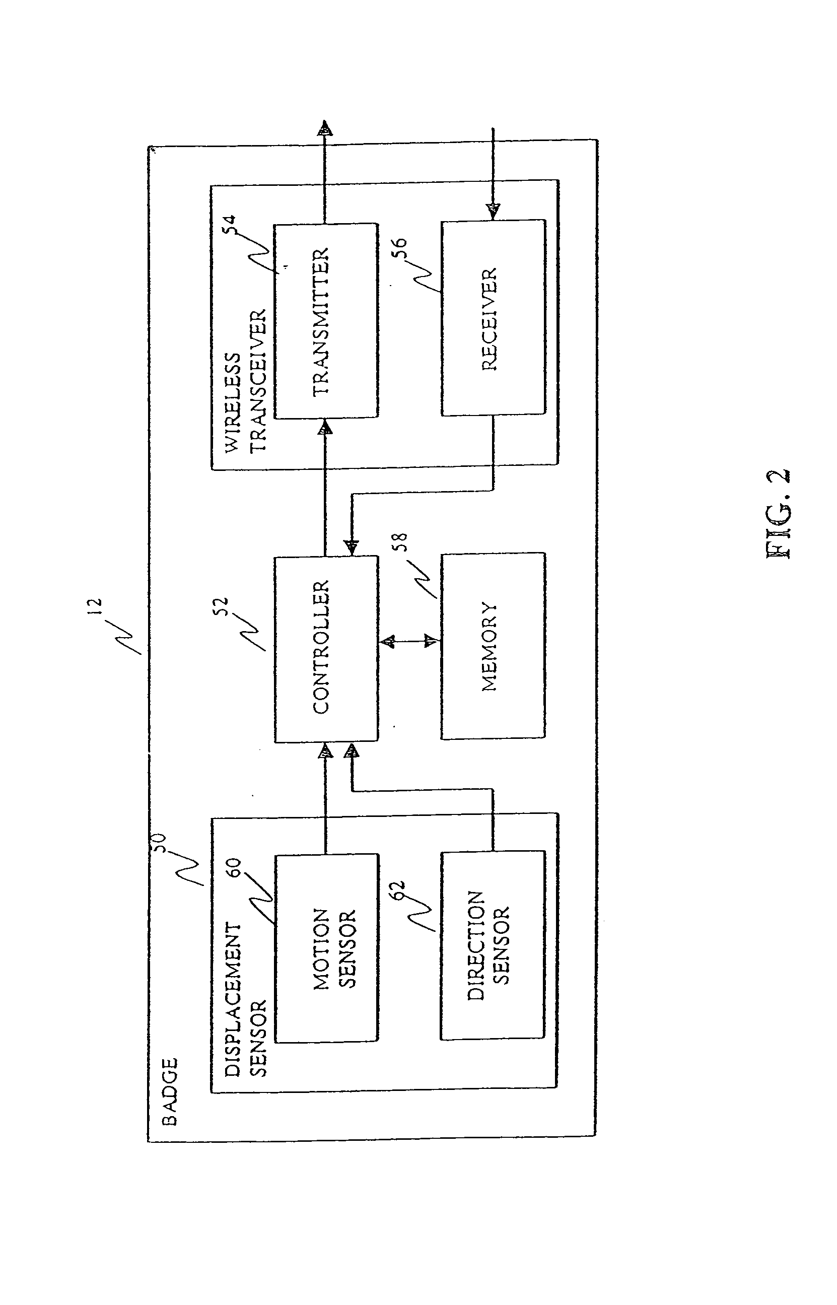
[0006]Pursuant to a first embodiment of the present invention there is provided a badge for tagging objects for use with a locating and / or activity based tracking system. The locating and / or activity based tracking system includes a master station and absolute reference point sensors that are in communication with the master station. The absolute reference point sensors are configured to receive tag ID information from the badge whenever the badge passes within a predefined range of the absolute reference point sensor. The absolute reference point sensors provide the master station with the received tag ID information and information identifying the particular absolute reference point sensor that received the tag ID information. From this received information, the master station determines a reference location for the badge and the associated tagged object that corresponds to the absolute reference point sensor that received the tag ID information. The badge further includes a displacement sensor that generates signals indicative of motion and heading of the badge. The transmitter periodically transmits the motion and heading information to the master station which enables the master station to update the location of the object in relation to a previously known location for the object.
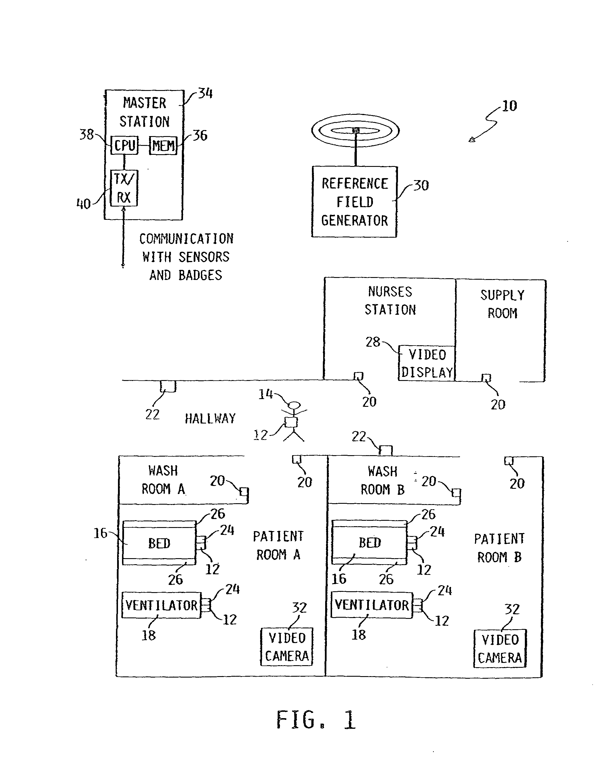
[0008]Pursuant to another embodiment of the invention there is provided an activity based tracking system that aids a caregiver in preventing a patient from falling from bed. In general, a master station of the activity based tracking system uses information received from badges and equipment sensors to detect whether a patient is lying near or moving toward a bed side rail that is in a down position. If the master station determines that a patient is lying near or moving toward a bed side rail in the down position, then the master station causes a fall prevention notification to be sent to the caregiver assigned to care for the identified patient.

Problems solved by technology

Caregivers such as nurses and other staff in a hospital ward, hospital wing, or other healthcare facility generally work under high pressure, high stress and long hours.
As alluded to above, caregiver (e.g., nurse) to patient ratios continue to decline due to increasing economic pressures.
However, conventional uses of computers in the above locating and identification systems only supply the caregivers with information and at the most alarms indicating possible adverse events.

Method used


Image

  • Article locating and tracking system
  • Article locating and tracking system
  • Article locating and tracking system

Examples


Embodiment Construction

[0020]While the invention is susceptible to various modifications and alternative forms, exemplary embodiments thereof have been shown by way of example in the drawings and will herein be described in detail. It should be understood, however, that there is no intent to limit the invention to the particular forms disclosed, but on the contrary, the intention is to cover all modifications, equivalents, and alternatives falling within the spirit and scope of the invention as defined by the appended claims.

[0021]FIG. 1 illustrates an exemplary activity based tracking (ABT) system 10 which incorporates various features of the present invention therein. In general, the ABT system 10 is operable to monitor activities and cause execution of actions in response to various activities. The exemplary ABT system 10 includes badges 12 used to tag persons 14 and equipment such as beds 16 and ventilators 18. As further described below, badges 12 may include passive RFID, active RF, or active IR tra...


PUM


Abstract

A system for tracking an activity in a healthcare environment includes a master station having a processor, a memory, and a transceiver, badges coupled to objects, each transmitting a unique badge ID, and sensors disposed throughout the environment, each including a transceiver for receiving badge IDs and transmitting to the master station transceiver the badge IDs and a unique sensor ID that relates the sensor to a location. The master station processor determines object locations from the badge and sensor IDs by identifying the badge associated with the object, relating the sensor ID to the sensor location, and storing object location information in memory. Each badge also includes a displacement sensor that generates signals indicating object movement and direction for transmission to the sensor transceivers which forward displacement information to the master station. The master station processor uses the information to update the stored object location information.

Description

TECHNICAL FIELD OF THE INVENTION[0001]This application claims priority of U.S. Patent Application Ser. No. 60 / 289,432, filed May 8, 2001, the disclosure of which is expressly incorporated herein by reference. The present invention is related to monitoring activities and more particularly monitoring activities of persons and equipment in a healthcare environment.BACKGROUND AND SUMMARY OF THE INVENTION[0002]Caregivers such as nurses and other staff in a hospital ward, hospital wing, or other healthcare facility generally work under high pressure, high stress and long hours. These caregivers should be highly responsive to patient needs, in non-emergency as well as emergency situations. Due to ever-increasing costs of healthcare and other economic practicalities, efficient deployment of the caregivers in a healthcare facility is desired, particularly at night when the number of caregivers is typically maintained at a minimum. Nevertheless, optimizing efficiency is of secondary importanc...

Claims


Application Information

Patent Timeline
Patent Type & Authority Patents(United States)
IPC IPC(8): G06N5/00G06F19/00G06K7/00G06K17/00G07C1/10G07C9/00
CPCG06F19/327G06K7/0008G06K7/10079G07C1/10G07C9/00111G08B13/2417G08B13/2462G08B21/245G06F19/3456G06K2017/0045G16H40/20G07C9/28
Inventor WILDMAN, TIMOTHY D.
Owner HILL ROM SERVICES
Learn More