In-die hydropiercing device for piercing holes in hydroformed parts

a hydro-formed part and in-die technology, applied in stripping devices, metal working devices, manufacturing tools, etc., can solve the problems of reducing both the power and stroke and achieve the effect of reducing both the power and stroke required, and the power requirements and the stroke required of the hydraulic cylinder strok

Inactive Publication Date: 2007-07-31
GM GLOBAL TECH OPERATIONS LLC
View PDF7 Cites 12 Cited by
  • Summary
  • Abstract
  • Description
  • Claims
  • Application Information

AI Technical Summary

Benefits of technology

[0008]As disclosed in another exemplary embodiment of the invention, the power requirements and the stroke required of the hydraulic cylinder stroke are further minimized by the addition of a pre-piercing operation that weakens an annular portion of the wall of the part where the punch blade eventually enters during the piercing operation. In this embodiment, the center support member is fixed in the one die in a position so that its face is spaced a predetermined distance backward from the die button face and the surrounding die cavity surface. And the punch is initially positioned by the hydraulic cylinder so that the punch blade shearing edge is also spaced a like distance backward from the die button face. As a result, the annular wall section of the part between the center support member face and the die button face and opposite the punch blade is stretched outwardly and forced over a sharp outer edge of the central die button bore during the hydroforming of the part. Which has the effect of significantly weakening this wall area close to the point of shearing away or breaking prior to penetration by the annular punch blade and its operation which also effects sealing with respect to the part and the slug in a manner like the afore-mentioned embodiment but with less inward extrusion of the hole edge and slug edge required for the sealing effect. And as a result, this embodiment significantly reduces both the power and stroke required of the hydraulic cylinder as compared with no such pre-piercing operation.

Problems solved by technology

And as a result, this embodiment significantly reduces both the power and stroke required of the hydraulic cylinder as compared with no such pre-piercing operation.

Method used


Image

  • In-die hydropiercing device for piercing holes in hydroformed parts
  • In-die hydropiercing device for piercing holes in hydroformed parts
  • In-die hydropiercing device for piercing holes in hydroformed parts

Examples


Embodiment Construction

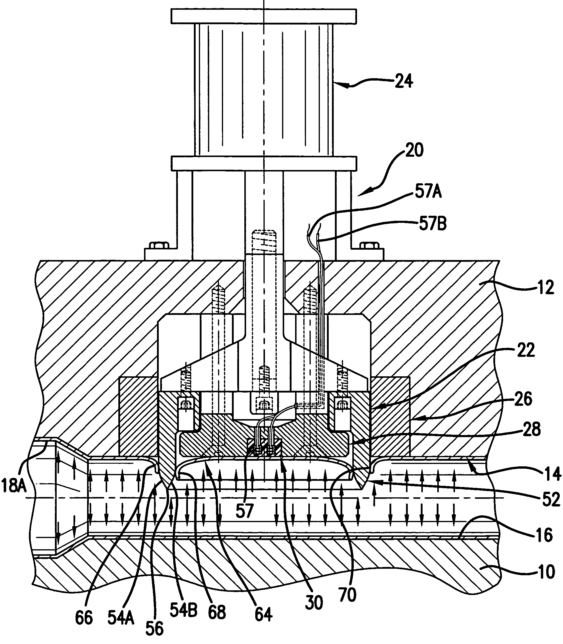
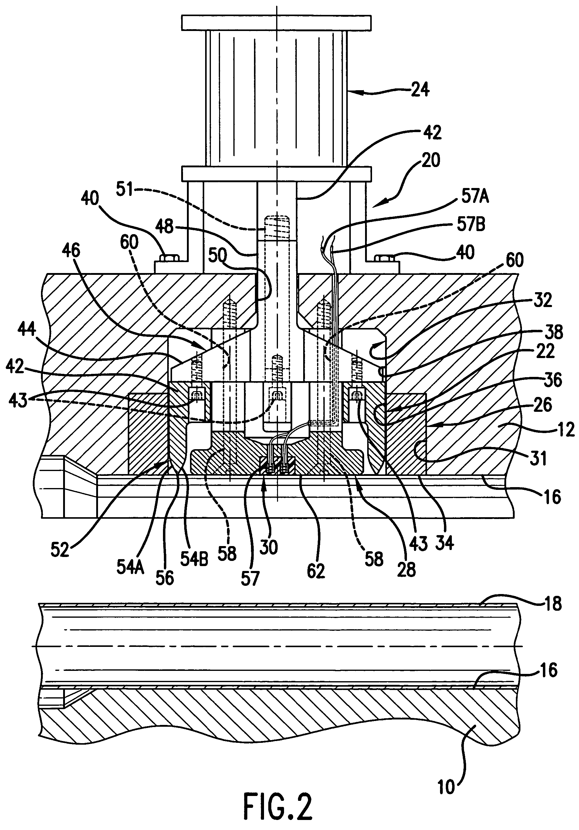
[0028]Referring to FIGS. 2-9, there is shown an intermediate portion of a conventional hydroforming apparatus comprising a lower die 10 and upper die 12 that when closed co-operatively defined a die cavity 14 (see FIGS. 4-7) having a surface 16 conforming to the required shape of the finished part. In the hydroforming process, a piece 18 of tubular metal stock is located in the lower die 10 as shown in FIG. 2 and the upper die 12 is then lowered to form the die cavity 14 about the piece 18 as shown in FIG. 4. A suitable hydroforming fluid, typically in the form of a water based liquid solution, is then delivered to the interior of the captured piece 18 through one end thereof while the other end is closed. With the hydroforming fluid thus delivered being raised to a pressure sufficient to forcibly expand the wall of the piece outward to conform to the die cavity surface 16 to thereby form a hydroformed part 18A as shown in FIG. 5. Following the formation of a required hole in the pa...


PUM

PropertyMeasurementUnit
pressureaaaaaaaaaa
pressureaaaaaaaaaa
sizeaaaaaaaaaa

Abstract

An in-die hydropiercing device comprises a punch with an annular shearing blade which is operated by a hydraulic cylinder and is received in a ring-shaped die button mounted in one of the dies that form a die cavity for the hydroforming of a part, a center support member that is received in the center of the punch and supports the wall of the part inward of the shearing blade during the hydroforming of the part and also during the piercing of the part with the shearing blade, a slug collector, and a slug retainer that is mounted on the center support member and provides for retention of a slug produced from the piercing operation against the center support member and later releases the slug onto the slug collector for disposal following the opening of the dies and insertion of the slug collector between the open dies and then retraction of the slug collector with the slug for slug disposal.

Description

TECHNICAL FIELD[0001]This invention relates to the piercing of holes in hydroformed parts while the parts remain in the hydroforming dies and more particularly to the devices used for such piercing.BACKGROUND OF THE INVENTION[0002]In the formation of one or more required holes in a hydroformed metal part, it is well known that the holes can be formed with a punch in a piercing operation on the part. While the part remains in the hydroforming dies following its hydroforming to the required shape and with the support of the internal hydroforming pressure. For example, there is shown in FIG. 1 of the accompanying drawings a prior art device that performs such a piercing operation. With such operation and the device for accomplishing it also being referred to herein as “hydropiercing” and “in-die hydropiercing device”, respectively.[0003]In the exemplary prior art device in FIG. 1, the piercing is performed on a hydroformed part A while the part remains in the hydroforming dies B and C ...

Claims


Application Information

Patent Timeline
Patent Type & Authority Patents(United States)
IPC IPC(8): B21D28/18B21D28/28
CPCB21D28/28Y10T29/49805Y10T83/0591
Inventor GHIRAN, MIRCEA M.HARMON, GERRY A.
Owner GM GLOBAL TECH OPERATIONS LLC
Why Eureka
Try Eureka