

Adjustable light beam device for aimable vehicle lamp assembly and method
a technology for vehicle lamps and light beams, applied in the direction of vehicle spotlighting, coupling device connections, lighting support devices, etc., can solve the problems of increasing packaging space requirements, increasing costs, and limiting the ability to adjust the width of light beams
- Summary
- Abstract
- Description
- Claims
- Application Information
AI Technical Summary
Benefits of technology
Problems solved by technology
Method used
Image

Examples
Embodiment Construction
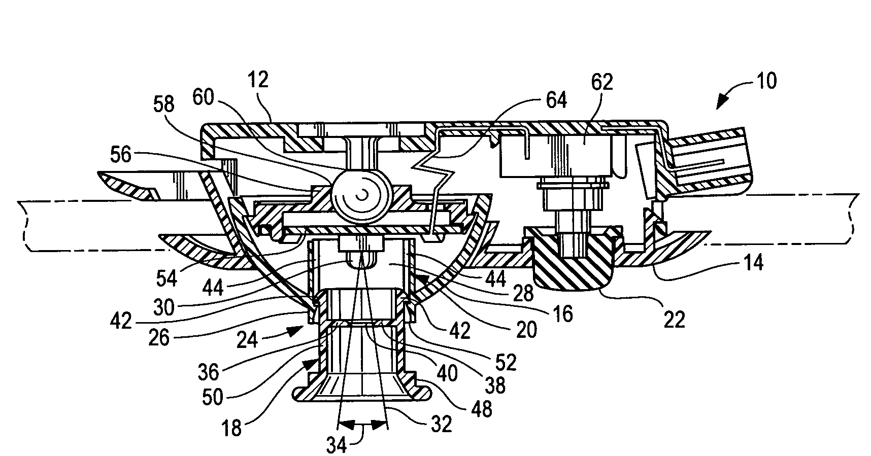
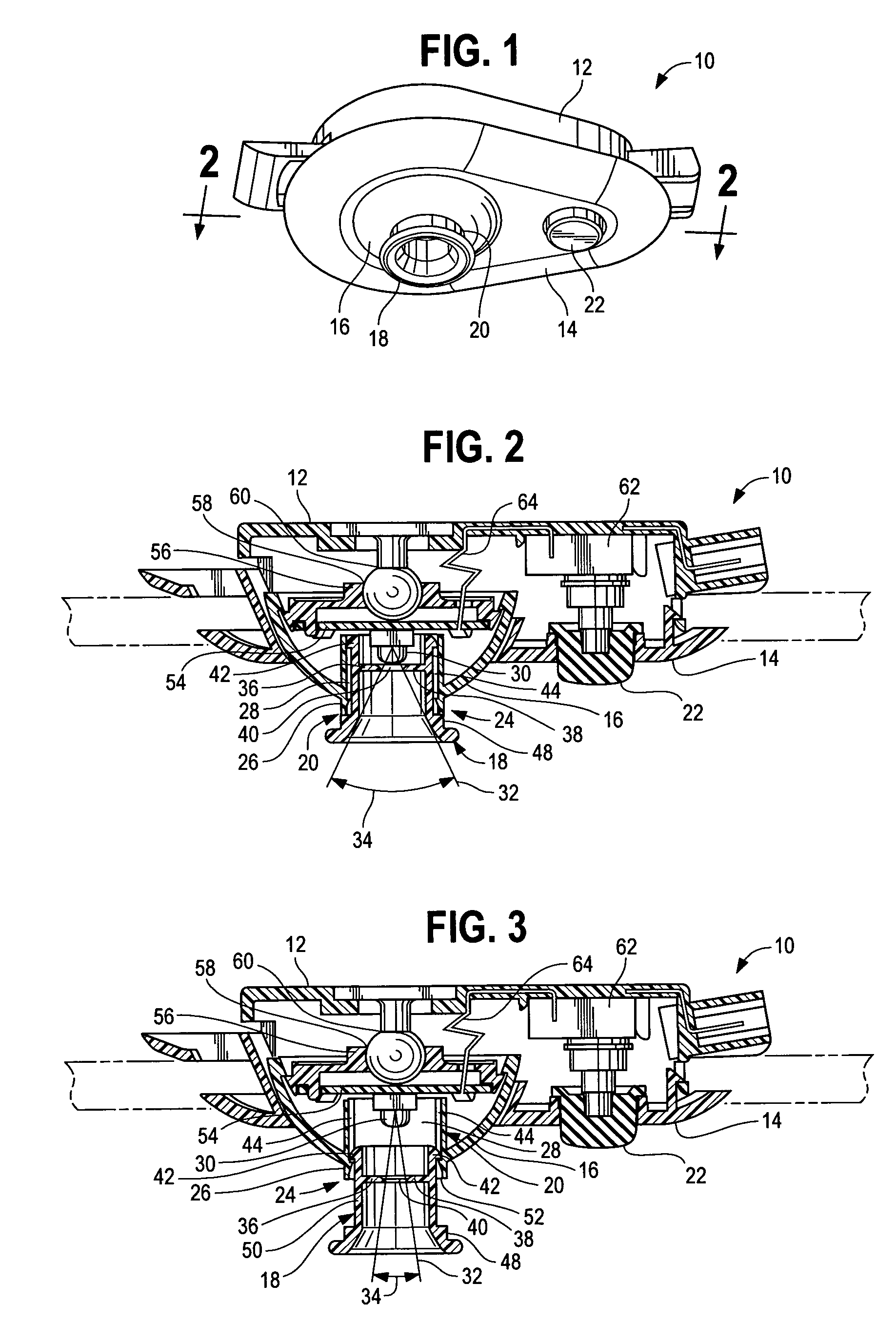
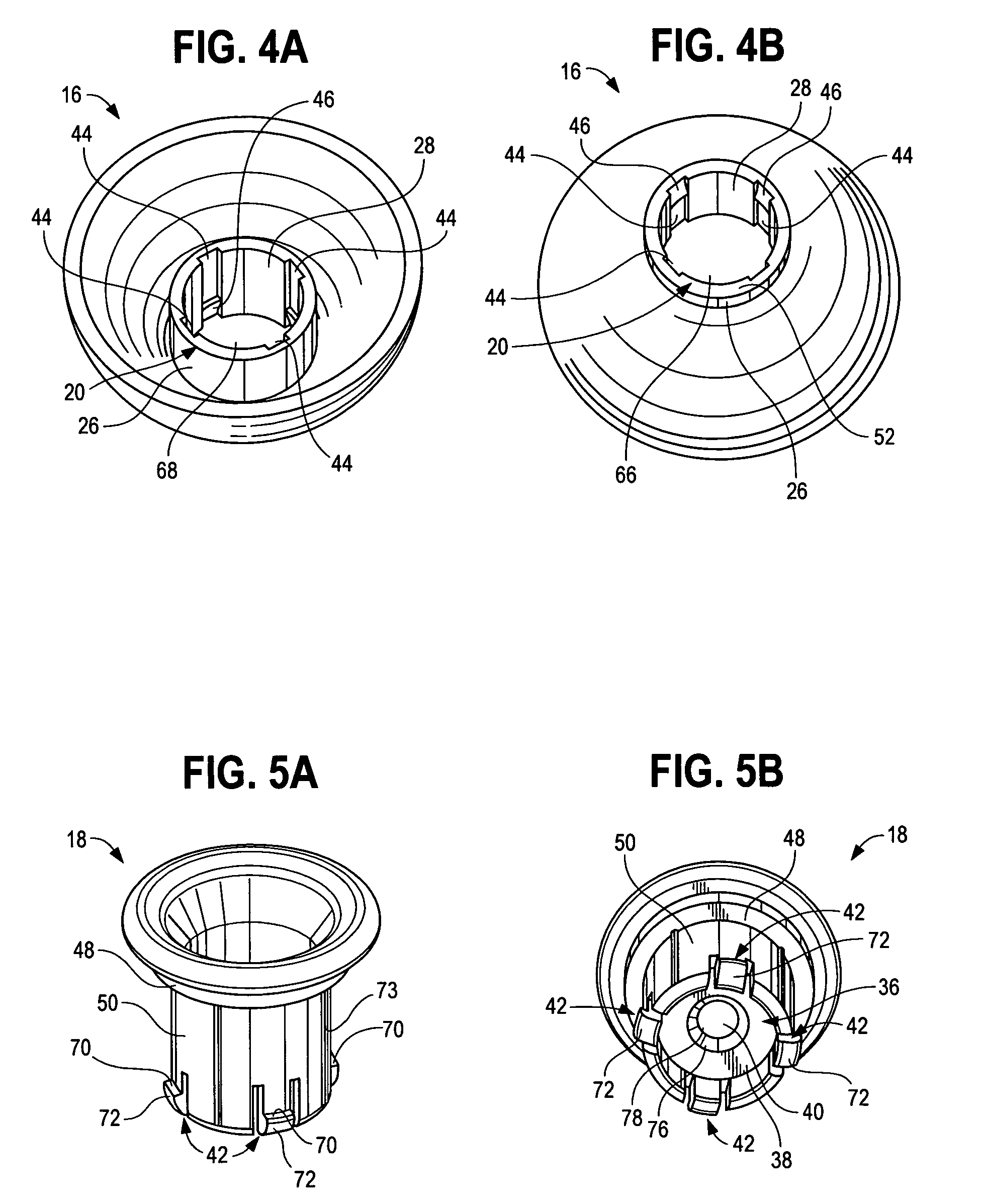
[0014]Referring now to FIG. 1, an aimable vehicle lamp assembly 10 is shown having a backplate 12 and a front bezel 14. Lamp housing 16 partially protrudes through the bezel 14. A movable tube component 18 is positioned within a channel member 20 of the lamp housing 16 which houses a light source that emits light through the tube component. Push button 22, partially extending through the front bezel 14, is connected to a switch unit which activates and deactivates the light source upon user actuation of the push button. The tube component 18 is able to be adjustably moved within the channel member 20 by sliding the tube component from a compact position (as seen in FIGS. 1 and 2) to a fully extended position (as seen in FIG. 3). The diameter of a beam of light projected from the tube component 18 is adjustably varied as the tube component is moved upwards and downwards in the lamp housing 16 such that the light beam has a relatively wide diameter when the tube component is placed in...
PUM
 Abstract
Description
Claims
Application Information