Crash energy absorption member

a technology of energy absorption and member, applied in the direction of shock absorbers, elastic dampers, roofs, etc., can solve the problem of decreasing the performance of crash energy absorption

Active Publication Date: 2007-08-07
NIPPON STEEL CORP +1
View PDF14 Cites 70 Cited by
  • Summary
  • Abstract
  • Description
  • Claims
  • Application Information

AI Technical Summary

Benefits of technology

[0019](I) By providing a crash energy absorption member with a transverse cross-sectional shape which satisfies all the following conditions (a) to (c), namely, (a) forming a closed cross section having a generally polygonal shape, (b) having no outwardly extending flange, and (c) having a groove in a region of at least one side of a basic cross section in a location not at an end point of the side, with the groove being recessed towards the interior of the basic cross section, the basic cross section being defined as the polygon having the largest area of the polygons obtained by connecting with straight lines some of a plurality of vertices constituting the generally polygonal shape, even in the case of a flat transverse cross-sectional shape which is frequently used in actual crash energy absorption members, a prescribed crash energy absorbing performance can be secured due to stable buckling in the axial direction into the shape of a bellows without leading to an increase in weight due to the addition of a partition or an increase in plate thickness and without causing bending deformation in the axial direction.

Problems solved by technology

If these conditions are deviated from, buckling behavior becomes unstable, and there is the possibility of crash energy absorbing performance decreasing.

Method used


Image

  • Crash energy absorption member
  • Crash energy absorption member
  • Crash energy absorption member

Examples


first embodiment

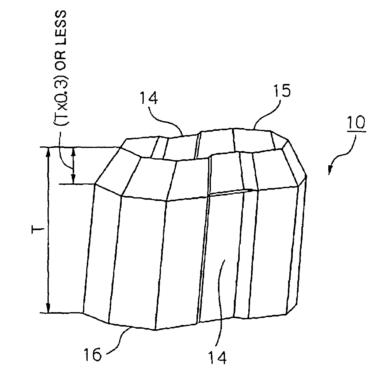
[0042]Next, best modes for carrying out a crash energy absorption member according to the present invention will be described in detail while referring to the attached drawings. In an explanation of this first embodiment, an example will be given of the case in which in a transverse cross section, in a region of at least one side of a basic cross section defined as the polygon having the largest area of polygons obtained by connecting with straight lines some of a plurality of vertices forming a generally polygonal shape having a closed cross section, a groove having a shape recessed towards the interior of the outline of the basic cross section is provided in a location other than at an end point of the side, and remaining regions other than the region of the side are formed as straight lines.

[0043]The crash energy absorption member of this embodiment is one which receives an impact load which is applied in the axial direction and absorbs impact energy by buckling into a bellows sh...

second embodiment

[0091]Next, a crash energy absorption member 10-1 according to a second embodiment will be explained.

[0092]This embodiment is similar to the first embodiment in that in a region of at least one side of a basic cross section defined as the polygon having the largest area of the polygons obtained by connecting with straight lines some of a plurality of vertices constituting a generally polygonal shape forming a closed cross section, a groove which is recessed towards the interior of the basic cross section is provided in a location not including an end point of the side.

[0093]However, in this embodiment, the remaining regions other than the above region are not formed as straight lines as in the first embodiment but are formed into a generally straight shape which projects to the outside of the basic cross section or a generally straight shape which is recessed towards the inside of the basic cross section, whereby the above-described first embodiment is further developed and improved...

example 1

[0117]Next, the present invention will be explained in further detail while referring to examples.

[0118]In this example, a collision test was carried out in the following manner in order to verify the results of a crash energy absorption member of the above-described first embodiment.

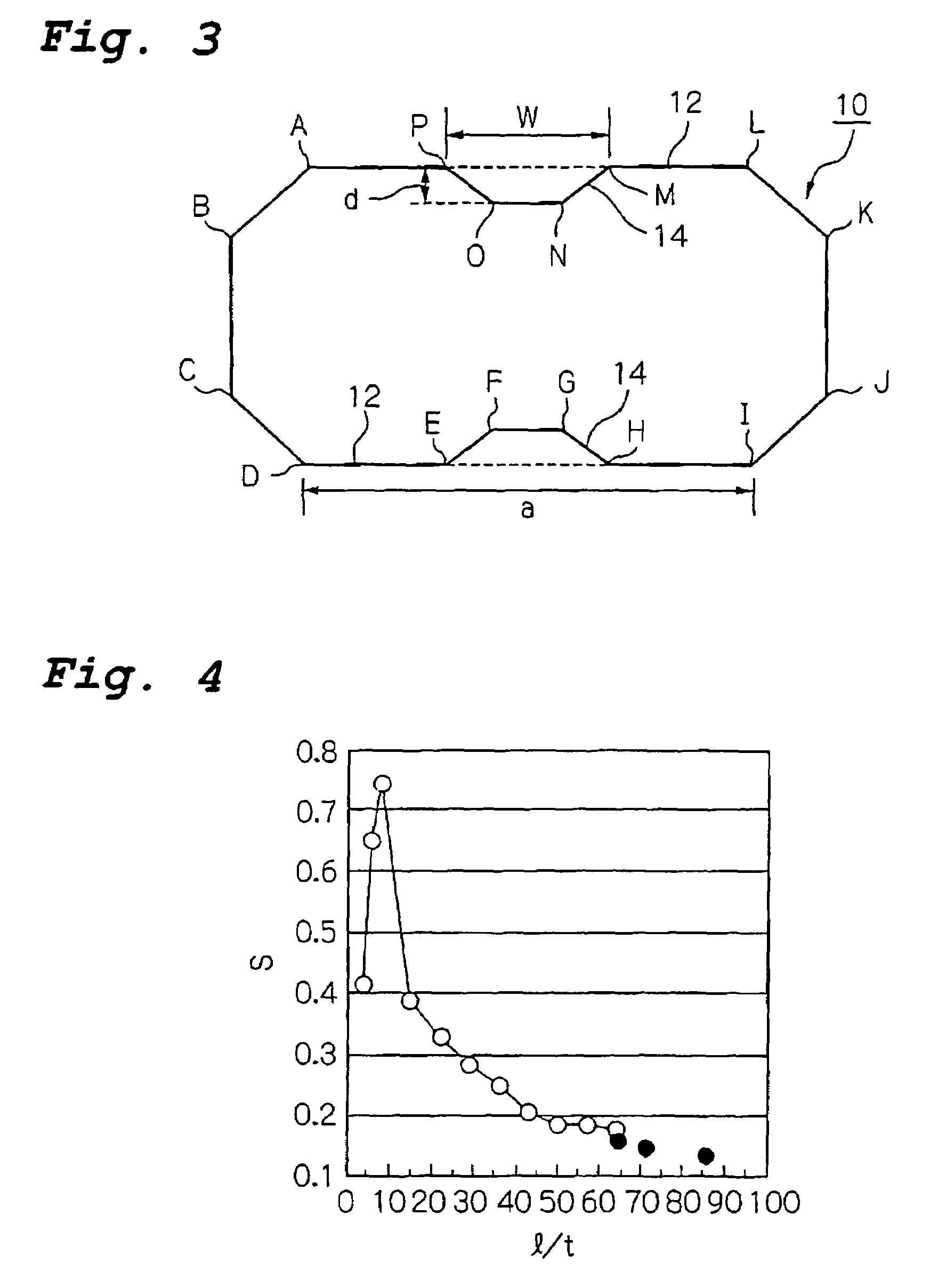
[0119]A high tensile strength steel sheet with a sheet thickness of 1.6 mm and a strength on the order of 590 MPa was subjected to bending to form a polygonal cross section, and the abutting surfaces were welded to form a crash energy absorption member 10 comprising a tubular body having the transverse cross-sectional shape shown in FIG. 14. As shown in FIG. 14, the length of one section of a side which was divided into two sections by a groove 14 formed therein was X5, the length of the other section was X6, and the depth of the groove was d.

[0120]A weight body having a weight of 200 kgf was dropped in free fall from a height of 11.9 m onto the crash energy absorption member 10. It impacted the crash e...


PUM


Abstract

A crash energy absorption member formed from a tubular body for absorbing impact energy by buckling when it receives an impact load in the axial direction from one end in the axial direction. It has a transverse cross-sectional shape along at least a portion in the axial direction which is a closed cross section having a plurality of vertices in which there is no flange on the outside of the closed cross section, and in a region of at least one side of a basic cross section formed from the largest outline obtained by connecting a portion of the plurality of vertices by straight lines, a groove which is recessed towards the inside of the outline is provided in a location other than at an end point of the side. Thus, the crash energy absorption member can achieve a prescribed amount of shock absorption by stably buckling in the axial direction without bending and without an increase in weight due to the addition of a partition or due to an increase in plate thickness.

Description

CROSS REFERENCES TO RELATED APPLICATIONS[0001]This application is a continuation of International Patent Application No. PCT / JP2004 / 011118, filed Jul. 28, 2004. This PCT application was not in English as published under PCT Article 21(2).TECHNICAL FIELD[0002]This invention relates to a crash energy absorption member. Specifically, this invention relates to a crash energy absorption member which can absorb impact energy which is generated at the time of a collision of a vehicle such as an automobile.BACKGROUND ART[0003]As is well known, at present, the bodies of many automobiles are monocoque bodies in which a load is supported by the overall body which is integral with a frame in order to achieve both a decrease in weight and high stiffness. The body of an automobile must be able to suppress impairment of the functions of the vehicle at the time of a collision of the vehicle and protect the lives of passengers within a passenger cabin. In order to decrease damage to a passenger cabi...

Claims


Application Information

Patent Timeline
Patent Type & Authority Patents(United States)
IPC IPC(8): B60R19/34F16F7/12
CPCF16F7/12F16F7/123
Inventor TAMURA, KENJINAKAZAWA, YOSHIAKIYOSHIDA, MICHITAKATAKAGI, KATSUTOSHIKANO, MITSUTOSHI
Owner NIPPON STEEL CORP
Why Eureka
Try Eureka