Droplet jetting apparatus, method of operating droplet jetting apparatus, and device manufacturing method

a technology of droplet jetting and droplet, which is applied in the direction of liquid surface applicators, coatings, printing, etc., to achieve the effects of reducing throughput, reducing device manufacturing costs, and efficient manufacturing

Active Publication Date: 2007-08-14
KATEEVA
View PDF3 Cites 15 Cited by
  • Summary
  • Abstract
  • Description
  • Claims
  • Application Information

AI Technical Summary

Benefits of technology

[0012]In consideration of the above circumstances, an object of the present invention is to provide (i) a droplet jetting apparatus in which moisture retentive liquid can be supplied to a capping portion while maintaining the sealed state of the nozzle opening of the droplet jetting head by using a capping device, thereby effectively avoiding clogging in the nozzle opening or the like, and preventing useless consumption of the liquid or decrease in life of the droplet jetting head and the wiper, (ii) a method of operating the droplet jetting apparatus, and (iii) a device manufacturing method.
[0015]According to the above apparatus, the supply of the moisture retentive liquid to the inside of the space formed by the nozzle formation surface and the capping device is performed by the moisture retentive liquid supply device which is connected to the capping device; thus, the weight and the size of the droplet jetting head and its periphery (which is a movable body) are not specifically increased, and accordingly, increase in the cost for motors for driving the droplet jetting head is prevented, thereby effectively avoiding clogging in the nozzle opening of the droplet jetting head. In addition, it is unnecessary to move the droplet jetting head when the moisture retentive liquid is supplied.
[0017]In this case, the moisture retentive liquid can be supplied without separating the capping device from the droplet jetting head, that is, while maintaining the capped state of the nozzle opening. Therefore, even if the period of time in which the nozzle opening is capped is long, the moisture retentive liquid can be, supplied at regular intervals while maintaining the capped state, thereby reducing the number of times of cleaning. Therefore, it is possible to lengthen life of the wiper provided in a cleaning unit for executing the cleaning.
[0021]According to this structure, the kind of the moisture retentive liquid is considered in a determination process performed after printing. Therefore, according to the degree of dryness which varies depending on the moisture retentive liquid, the quantity or the time interval (for the supply operation) of the supplied moisture retentive liquid can be appropriately controlled, thereby reducing useless consumption of the moisture retentive liquid as much as possible and effectively avoiding clogging of the nozzle opening, or the like.
[0024]In this case, the moisture retentive liquid can be supplied without separating the capping device from the droplet jetting head, that is, while maintaining the capped state of the nozzle opening. Therefore, it is unnecessary to move the droplet jetting head when the moisture retentive liquid is supplied. In addition, even if the period of time in which the nozzle opening is capped is long, the moisture retentive liquid can be supplied at regular intervals while maintaining the capped state, thereby reducing the number of times of cleaning. Therefore, it is possible to lengthen life of the wiper provided in a cleaning unit for executing the cleaning.
[0028]In this case, a pattern is formed by jetting the predetermined liquid as droplets, and then the nozzle opening is capped by the capping device. After that, the moisture retentive liquid can be supplied without separating the capping device from the droplet jetting head; thus, it is unnecessary to move the droplet jetting head when the moisture retentive liquid is supplied. Accordingly, devices can be efficiently manufactured without reducing the throughput, thereby reducing the manufacturing cost for devices.

Problems solved by technology

In addition, it is unnecessary to move the droplet jetting head when the moisture retentive liquid is supplied.

Method used


Image

  • Droplet jetting apparatus, method of operating droplet jetting apparatus, and device manufacturing method
  • Droplet jetting apparatus, method of operating droplet jetting apparatus, and device manufacturing method
  • Droplet jetting apparatus, method of operating droplet jetting apparatus, and device manufacturing method

Examples


Embodiment Construction

[0036]Hereinafter, the droplet jetting apparatus, the method of operating the droplet jetting apparatus, and the device manufacturing method, as embodiments according to the present invention, will be explained in detail with reference to the drawings.

Droplet Jetting Apparatus

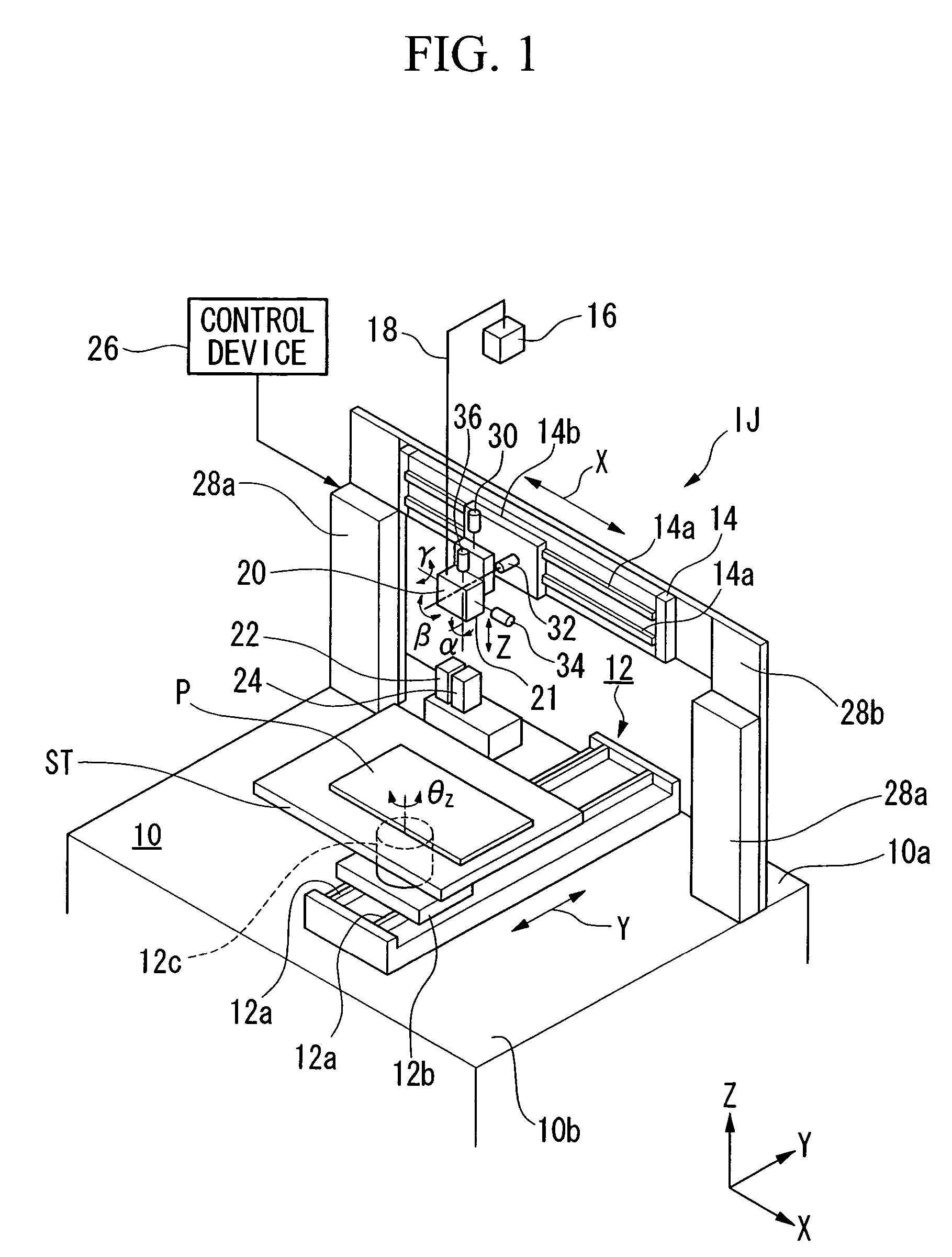
[0037]FIG. 1 is a perspective view showing the general structure of the droplet jetting apparatus as an embodiment of the present invention. In the following explanation, the XYZ orthogonal coordinate system is provided in the drawings where necessary, and the positional relationships between members are explained with reference to the XYZ orthogonal coordinate system. In the XYZ orthogonal coordinate system, the XY plane is defined as a plane parallel to the horizontal plane and the Z axis is defined in the upward vertical direction. In the present embodiment, the moving direction (i.e., the main scanning direction) of the jet head (i.e., droplet jetting head) 20 is defined as the X direction, and the moving d...


PUM


Abstract

A droplet jetting apparatus having a droplet jetting head including a nozzle opening formed in a nozzle formation surface, from which droplets of a predetermined liquid are jetted, and a capping device for capping the nozzle opening of the head. A moisture retentive liquid supply device connected to the capping device is provided for supplying a moisture retentive liquid with respect to the predetermined liquid to a space formed by the nozzle formation surface and the capping portion. The weight and the size of the head and its periphery, which is a movable body, are not specifically increased, and accordingly, increase in the cost for motors for driving the droplet jetting head is prevented, thereby effectively avoiding clogging in the nozzle opening of the droplet jetting head. In addition, it is unnecessary to move the droplet jetting head when the moisture retentive liquid is supplied.

Description

BACKGROUND OF THE INVENTION[0001]1. Field of the Invention[0002]The present invention relates to a droplet jetting apparatus having a droplet jetting head in which a specific liquid is jetted as droplets from nozzle openings and a capping device for capping a nozzle opening of the droplet jetting head so as to prevent drying of the liquid or clogging of the nozzle opening, and also relates to a method of operating the droplet jetting apparatus and to a device manufacturing method.[0003]Priority is claimed on Japanese Patent Application No. 2004-023872, filed Jan. 30, 2004, the content of which is incorporated herein by reference.[0004]2. Description of Related Art[0005]Generally, a droplet jetting head includes a pressure generating chamber for containing a specific liquid, a piezo actuator for compressing the pressure generating chamber, and a nozzle opening communicated with the pressure generating chamber. The liquid in the pressure generating chamber is compressed by the piezo a...

Claims


Application Information

Patent Timeline
Patent Type & Authority Patents(United States)
IPC IPC(8): B41J2/165B41J2/015B05C5/00B41J2/01B41J2/045
CPCB41J2/16552B41J2/16508B41J2/165
Inventor USUDA, HIDENORI
Owner KATEEVA
Why Eureka
Try Eureka