Electrophoretic display comprising optical biasing element

a technology of optical biasing element and electrophoretic display, which is applied in the field of electrophoretic display control, can solve the problems of physical barriers, inconvenient operation, and inconvenient use, and achieve the effects of reducing the number of electrodes

Inactive Publication Date: 2007-08-14
E INK CORPORATION
View PDF239 Cites 293 Cited by
  • Summary
  • Abstract
  • Description
  • Claims
  • Application Information

AI Technical Summary

Benefits of technology

[0141]Now referring to FIGS. 17-20, some display media include portions or components that do not contribute to the changing appearance of images displayed during operation of a display device. In particular, portions of a displayed image can have a fixed optical appearance. This effect can be described with reference to an illustrative display medium depicted in FIGS. 17A and 17B.

Problems solved by technology

Electrophoretic display media, generally characterized by the movement of particles in an applied electric field, are highly reflective, potentially bistable, and consume very little power.
Lateral migration of components of an electrophoretic medium, for example, particles in a fluid, can impair the performance of a display.
Physical barriers, however, present a new problem, because the barrier material typically is unresponsive to addressing of display elements.

Method used


Image

  • Electrophoretic display comprising optical biasing element
  • Electrophoretic display comprising optical biasing element
  • Electrophoretic display comprising optical biasing element

Examples


Embodiment Construction

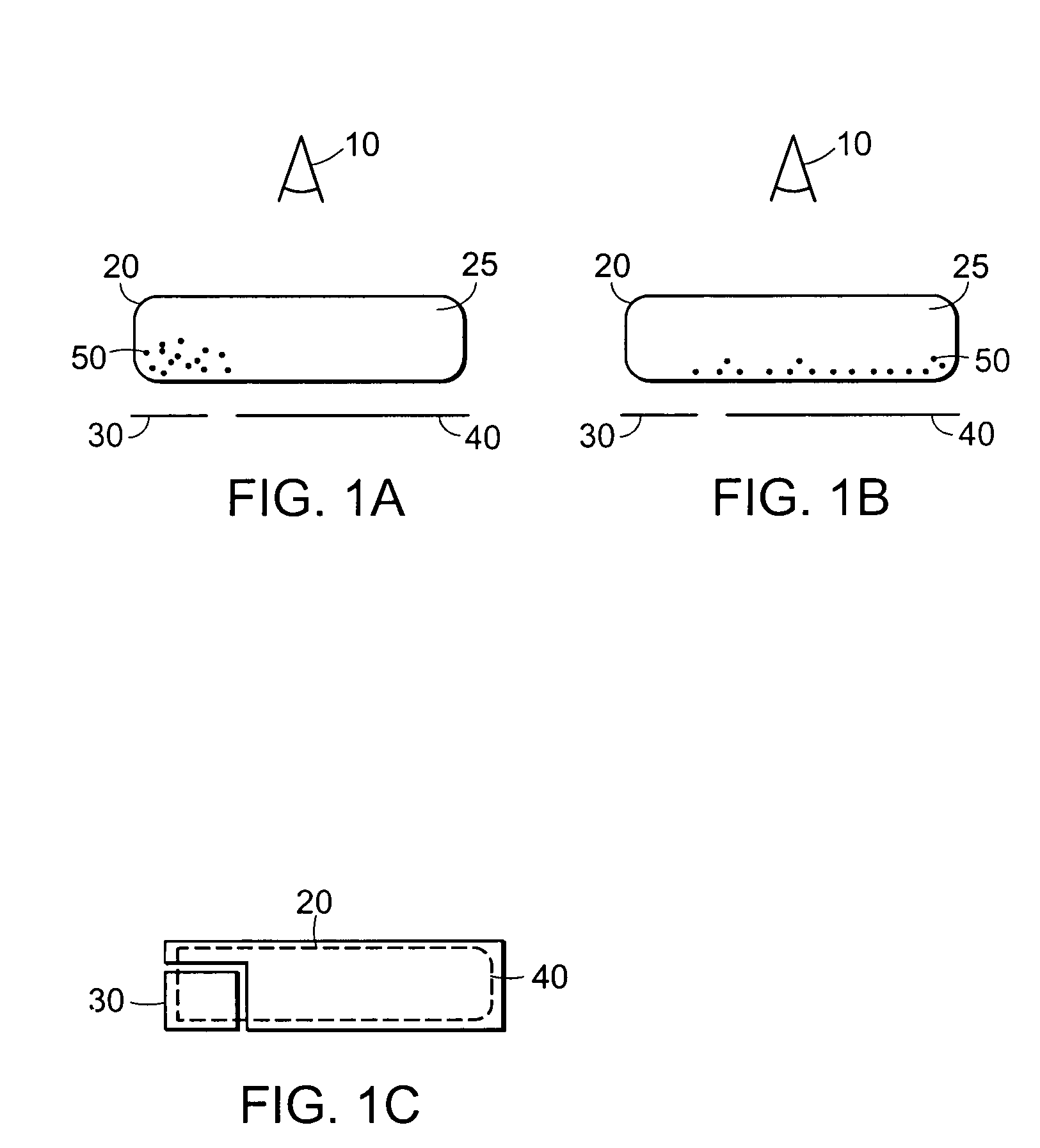
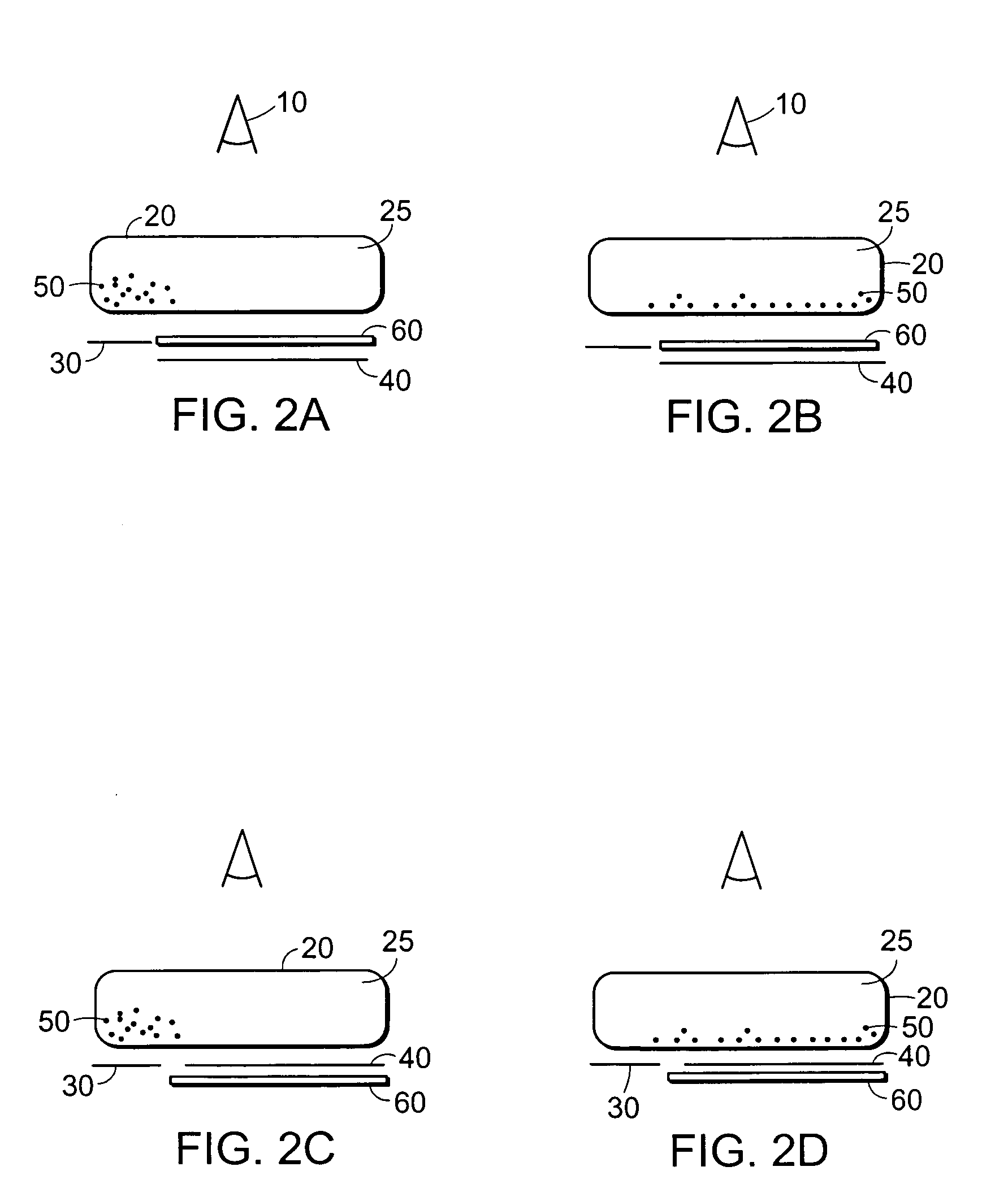
[0066]In the following, color electrophoretic displays are first described, with reference to FIGS. 1-16. Then, electrophoretic displays that include an optical biasing element are described, with reference to FIGS. 17-20.

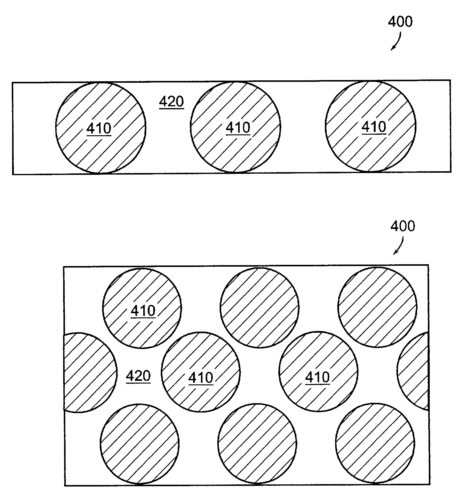
[0067]An electronic ink is an optoelectronically active material which comprises at least two phases: an electrophoretic contrast medium phase and a coating / binding phase. The electrophoretic phase comprises, in some embodiments, a single species of electrophoretic particles dispersed in a clear or dyed medium, or more than one species of electrophoretic particles having distinct physical and electrical characteristics dispersed in a clear or dyed medium. In some embodiments the electrophoretic phase is encapsulated, that is, there is a capsule wall phase, i.e., a membrane, between the two phases.

[0068]The coating / binding phase includes, in one embodiment, a polymer matrix that surrounds the electrophoretic phase. In this embodiment, the polymer in the polymeric bi...


PUM

PropertyMeasurementUnit
diametersaaaaaaaaaa
dielectric constantaaaaaaaaaa
specific gravityaaaaaaaaaa

Abstract

The invention features an electrophoretic display element. The display element includes an electrophoretic display medium, an optical biasing element to modify an optical characteristic of the electrophoretic display element, and an addressing electrode to address the electrophoretic display medium. The optical biasing element may include, for example, a distinct layer of material, or may include particles or molecules embedded in a layer of the display element.

Description

CROSS-REFERENCE TO RELATED APPLICATIONS[0001]This application is a continuation-in-part of U.S. Ser. No. 09 / 140,862, filed Aug. 27, 1998, now U.S. Pat. No. 7,167,155 the contents of which are incorporated herein by reference.FIELD OF THE INVENTION[0002]The present invention relates to electronic displays and, in particular, to the control of the optical characteristics of electrophoretic displays.BACKGROUND OF THE INVENTION[0003]Traditionally, electronic displays, such as liquid crystal displays, have been made by sandwiching an optoelectrically active display material between two pieces of glass. In many cases each piece of glass has an etched, clear electrode structure formed using indium tin oxide.[0004]A first electrode structure controls all the segments of the display that may be addressed, that is, changed from one visual state to another. A second electrode, sometimes called a counter electrode, addresses all display segments as one large electrode, and is generally designed...

Claims


Application Information

Patent Timeline
Patent Type & Authority Patents(United States)
IPC IPC(8): G09G3/34G02B26/00G02F1/167G02F1/16757G02F1/1677
CPCG02F1/167G02F1/16757G02F1/1677
Inventor ALBERT, JONATHAN D.COMISKEY, BARRETT
Owner E INK CORPORATION
Why Eureka
Try Eureka