

Double clutch transmission
a transmission and double clutch technology, applied in the direction of mechanical equipment, transportation and packaging, etc., can solve the problem that the transmission designed for a high-torque engine may easily become very large, and achieve the effect of enhancing the allowable range of a reduction ratio, reducing length, and enhancing power transmission efficiency
- Summary
- Abstract
- Description
- Claims
- Application Information
AI Technical Summary
Benefits of technology
Problems solved by technology
Method used
Image

Examples
first embodiment
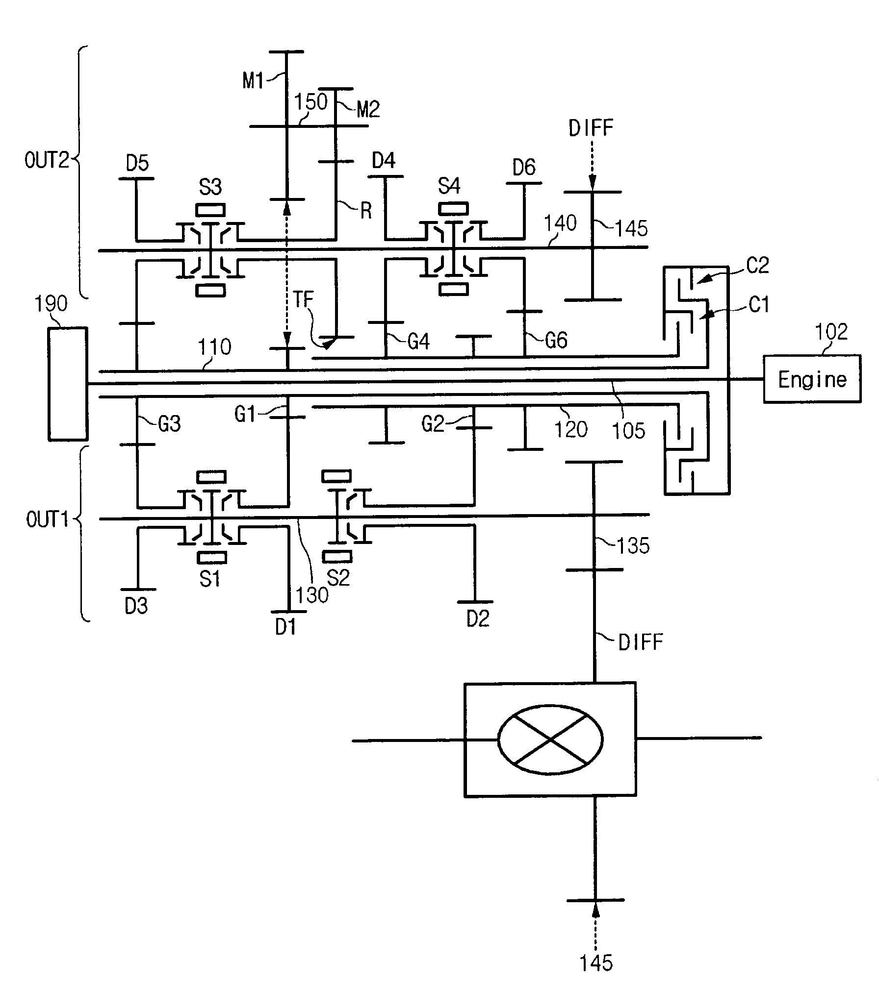
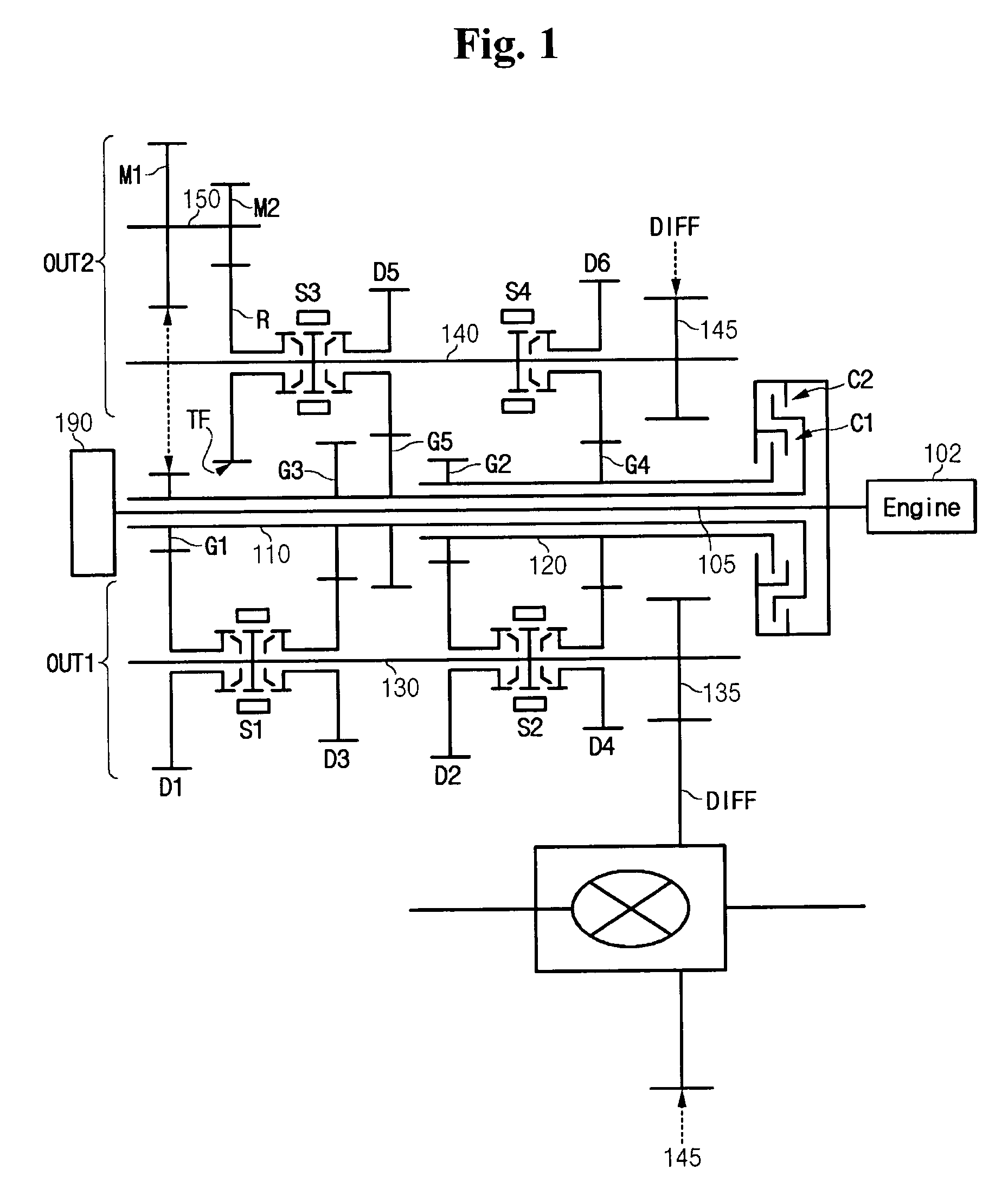
[0052]FIG. 1 is a schematic diagram of a double clutch transmission according to the present invention.
[0053]As shown in FIG. 1, a double clutch transmission according to a first embodiment of the present invention includes a main input shaft 105; first and second input shafts 110 and 120; first and second clutches C1 and C2; first, second, third, fourth, and fifth drive gears G1, G2, G3, G4, and G5; first and second output devices OUT1 and OUT2; and a differential gear DIFF.
[0054]The main input shaft 105 receives a torque from an engine 102. The first input shaft 110 may rotate coaxially about the main input shaft 105.
[0055]FIG. 1 illustrates that the main input shaft 105 penetrates through the first input shaft 110 to be connected to an oil pump 190. This is only to exemplarily show that a double clutch transmission of the present invention may be realized as a wet type. Therefore, it should not be understood that the scope of the present invention is limited to as shown in FIG. 1...
second embodiment
[0087]The first, third, and fifth drive gears G1, G3, and G5 are formed on the first input shaft 110, and the second and fourth drive gears G2 and G4 are formed on the second input shaft 120.
[0088]In further detail, the first, third, and fifth drive gears G1, G3, and G5 may be disposed on the first input shaft 110 such that an end of the second input shaft 120 is closest to the first drive gear G1, further to the third drive gear G3, and farthest from the fifth drive gear G5. In addition, the second and fourth drive gears G2 and G4 are disposed on the second input shaft 120 such that the engine 102 is closer to the fourth drive gear G4 than to the second drive gear G2. In other words, regarding disposition of such drive gears, referring to FIG. 3 related to a second embodiment of the present invention, the first, second, third, fourth, and fifth drive gears G1, G2, G3, G4, and G5 are disposed in a sequence of the fifth drive gear G5, the third drive gear G3, the first drive gear G1...
third embodiment
[0107]As shown in FIG. 4, a double clutch transmission according to the present invention further includes a first output device OUT1 and a second output device OUT2. The first output device OUT1 selectively changes torques of the first, second, third, and fourth drive gears G1, G2, G3, and G4, and outputs the changed torques. The second output device OUT2 selectively changes torques of the first, third, and fourth drive gears G1, G3, and G4, and outputs the changed torques.
[0108]As shown in FIG. 4, the first output device OUT1 includes a first output shaft 130; first, second, third, and fourth driven gears D1, D2, D3, and D4; first and second synchronizing devices S1 and S2; and a first output gear 135.
[0109]The first output shaft 130 is disposed parallel to and apart from the main input shaft 105 by a predetermined distance. The first, second, third, and fourth driven gears D1, D2, D3, and D4 are disposed on the first output shaft 130, and are respectively engaged with the first, ...
PUM
 Abstract
Description
Claims
Application Information