Check patentability & draft patents in minutes with Patsnap Eureka AI!

Method for leveling an object

a technology for leveling objects and objects, applied in the direction of lighting and heating equipment, gearing, domestic cooling equipment, etc., can solve the problems of uneven or sloping floors, many problems can develop, and affect the proper operation of the apparatus,

Inactive Publication Date: 2007-08-21
STURM RUGER & CO INC
View PDF26 Cites 11 Cited by
  • Summary
  • Abstract
  • Description
  • Claims
  • Application Information

AI Technical Summary

Benefits of technology

[0017]In accordance with one embodiment of the leveling device, a means may be connected to one end of the elevation shaft for protecting a nonuniform surface from damage by contact of the end of the shaft with the surface. In one embodiment, the surface protecting means may comprise a pad shaped as a round disk. In one embodiment, the elevation shaft is axially movable such that the pad may be completely retracted into the housing of the leveling device. In another embodiment, the pad may be rotably connected to the end of the elevation shaft to permit independent relative rotation between the pad and the shaft. The pad in yet another embodiment may be movably attached to the end of the elevation shaft to permit the pad to tilt at an angle relative to a plane perpendicular to the longitudinal axis of the shaft. In one embodiment, the angle may range from 0 to about 5 degrees.

Problems solved by technology

The need to install and level objects on uneven or sloping floors has presented a longstanding problem, especially for various types of apparatuses including machines and appliances.
If all the legs do not contact the floor, many problems can develop.
For example, the outer cabinet and frame of an apparatus may become distorted over time due to nonuniform weight support, thereby impairing the proper operation of the apparatus.
In the case of a motorized apparatus such as a washing machine, inadequate contact of all its legs with the floor is especially problematic because these devices have a tendency to vibrate and “walk” across the floor if the floor is not level.
Annoying “rocking” problems with an apparatus may also result where the legs do not all contact the floor.
Moreover, installations that are not level may be aesthetically undesirable by the inability to match the heights of adjacent cabinets, other equipment, or work surfaces.
Obviously, this technique has numerous drawbacks.
First, the apparatus must be manually lifted while such shims are placed under the legs, thereby often requiring more than one installer.
This situation also increases the potential risk of back or other physical injuries to the installers.
Second, the shims are not permanently mounted to the apparatus legs and may shift over time or become completely dislodged.
This is especially problematic with motorized apparatuses which vibrate and “walk” as described above.
These manually adjustable supports, however, are still plagued by many of the problems encountered with the shim technique described above.
Furthermore, there is usually no way to access the rear legs for adjustment once the apparatus is slid into its final position because access is often not available from the rear or sides of the apparatus.
The manually adjustable leg design is also cumbersome to use, involving a time consuming trial and error approach to leveling the apparatus on uneven floors.
Other approaches have been used with limited success in an attempt to overcome the many problems of leveling objects on uneven floors.
Although the rear supports are adjustable from the front of the appliance, the mechanism is complicated and requires virtually all parts to be fabricated from metal.
Like many similar mechanisms, the manufacturing costs are high and they are prone to problems due to their complex design.

Method used


Image

  • Method for leveling an object
  • Method for leveling an object
  • Method for leveling an object

Examples


Embodiment Construction

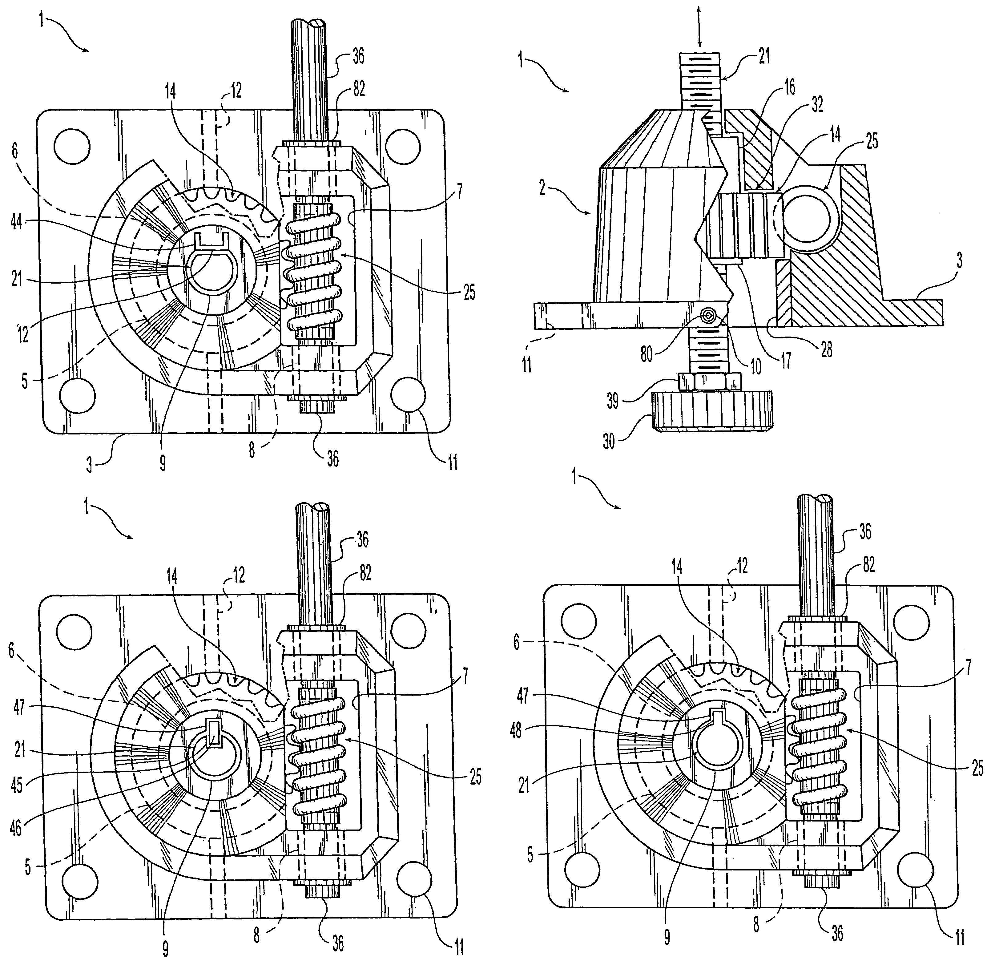
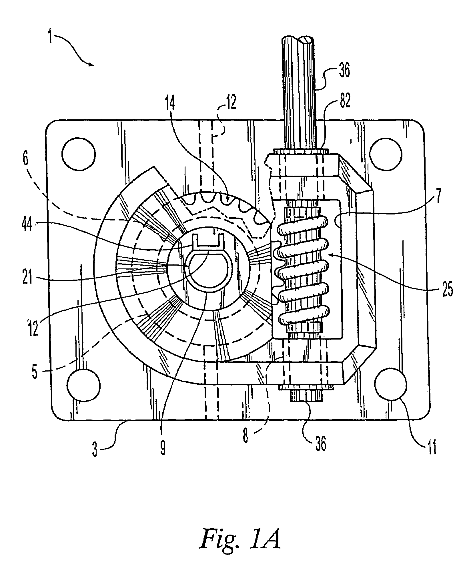
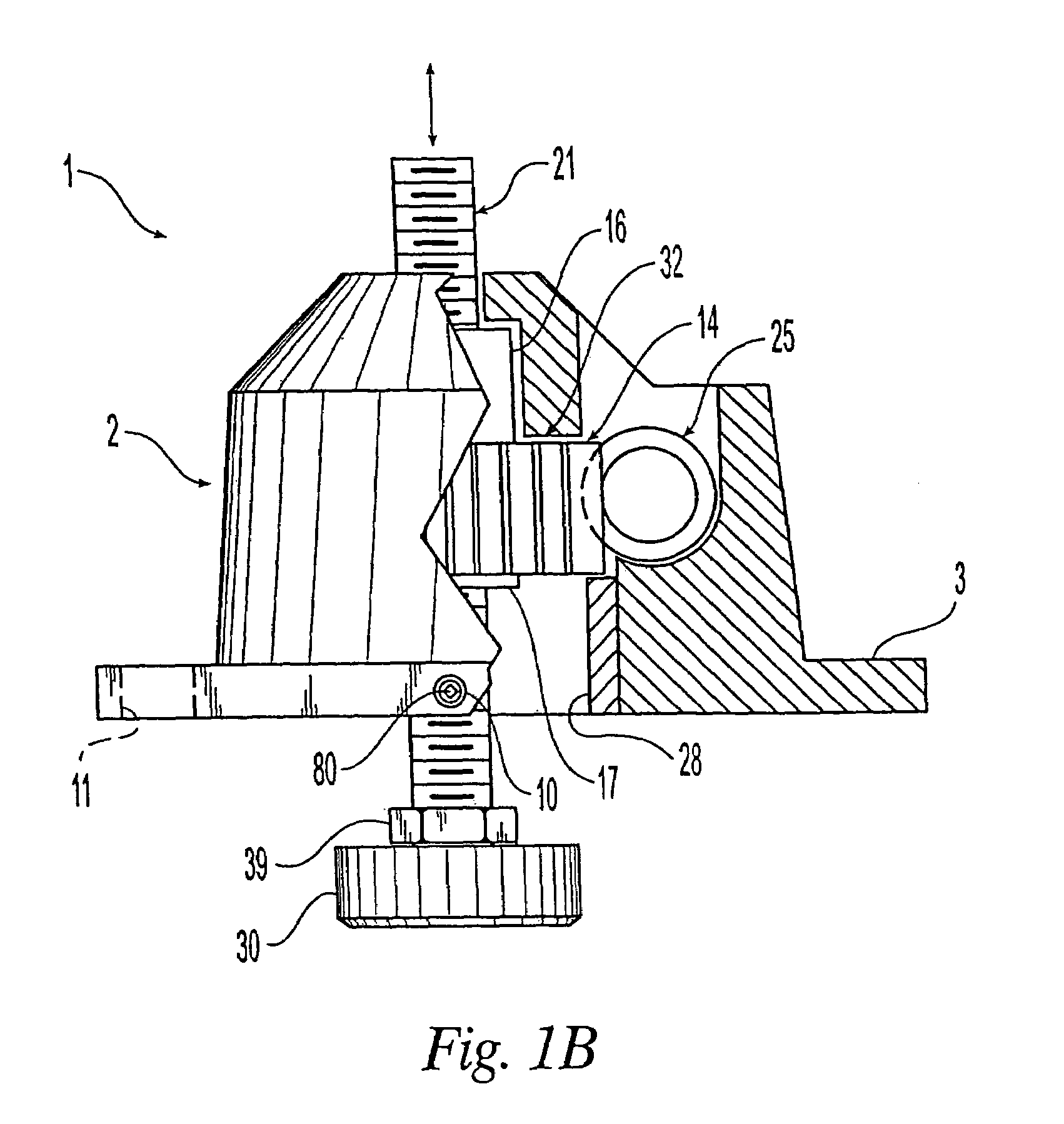
[0066]A first embodiment of the leveling device 1 is shown in FIGS. 1A& B as generally including a housing 2, a worm gear 25, a driven gear 14 having internal threads 61, and a threaded elevation shaft 21. A retaining collar 28 may be provided which holds the driven gear 14 inside the housing 2. A pad 30 may also be disposed on the lower end of the elevation shaft as shown. Leveling devices such as the present invention are installed on the bottom of an object, such as an appliance for example, where they function as a leg or support that may be adjusted to level the object when installed on a nonuniform surface. Basically, the leveling device 1 operates by rotating the worm gear 25 which causes concomitant rotations of the driven gear 14. The internal threads of the rotating driven gear 14 engage the threads of the elevation shaft 21. Since means are provided to prevent or restrain the shaft 21 from rotating in relation to the housing 2 (described hereafter), rotation of the driven...


PUM


Abstract

A device for leveling an object on uneven or sloping floors. The device is comprised of a housing with a substantially hollow portion having a worm gear, a driven gear, and an elevation shaft with threads on at least a portion of the shaft's external surface. The worm gear operably engages the driven gear, which in turn operably engages the elevation shaft. When the worm gear is rotated in opposite directions, concomitant rotations of the driven gear cause the elevation shaft to move axially up or down, thereby providing leveling motions to an object to which the device is attached. A pad may be attached to one end of the elevation to prevent scratching the surface on which the object rests. The hollow portion of the housing is configured to provide at least one load-bearing surface such that no separate bearings are required with the device.

Description

CROSS-REFERENCE TO RELATED APPLICATIONS[0001]This is a divisional of U.S. patent application Ser. No. 10 / 085,815 filed Feb. 26, 2002 now U.S. Pat. No. 6,729,590, entitled “Leveling Device,” which takes priority from U.S. Provisional Patent Application Ser. No. 60 / 351,472 filed Jan. 23, 2002, both of which are incorporated in their entirety herein by reference.FIELD OF THE INVENTION[0002]The present invention generally relates to a leveling device, and more particularly to an improved device for leveling objects that rest on a floor or other substantially horizontal, but yet uneven or sloping surface.BACKGROUND OF THE INVENTION[0003]The need to install and level objects on uneven or sloping floors has presented a longstanding problem, especially for various types of apparatuses including machines and appliances. Often floors are not plumb or perfectly flat, yet it is important that all the legs of an object contact the floor to provide adequate support and to equally distribute the w...

Claims


Application Information

Patent Timeline
Patent Type & Authority Patents(United States)
IPC IPC(8): F16M11/24B66F3/16A47L15/42D06F39/12F16M7/00F16M11/42F25D23/00
CPCA47L15/4253D06F39/125F16M7/00F16M11/42F16M11/18Y10T74/18792F25D2323/0011F16M2200/08F25D23/00
Inventor GABRIEL, EDWARD
Owner STURM RUGER & CO INC
Features
  • R&D
  • Intellectual Property
  • Life Sciences
  • Materials
  • Tech Scout
  • Unparalleled Data Quality
  • Higher Quality Content
  • 60% Fewer Hallucinations
Learn More