

Laryngoscope blade
- Summary
- Abstract
- Description
- Claims
- Application Information
AI Technical Summary
Benefits of technology
Problems solved by technology
Method used
Image

Examples
second embodiment
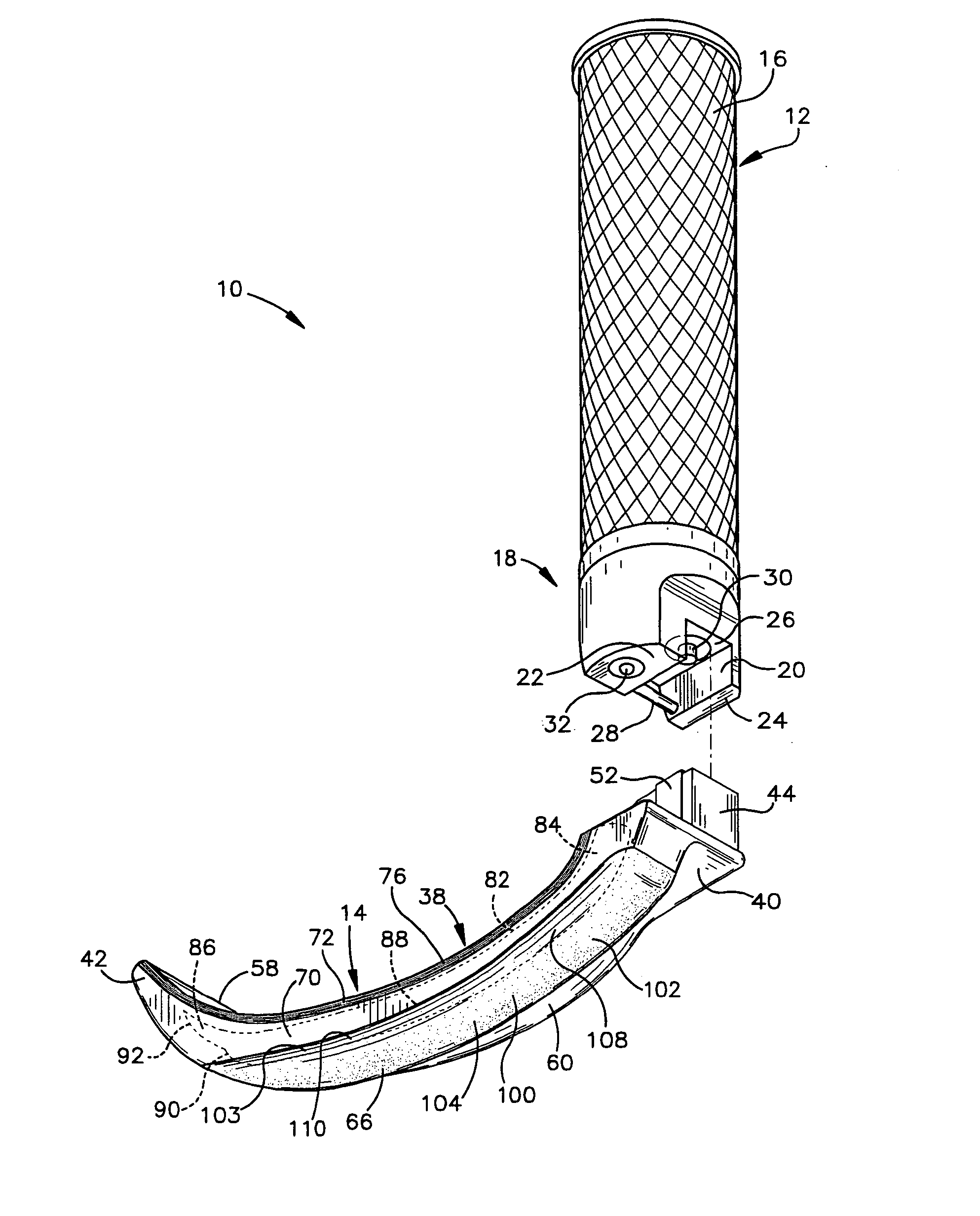
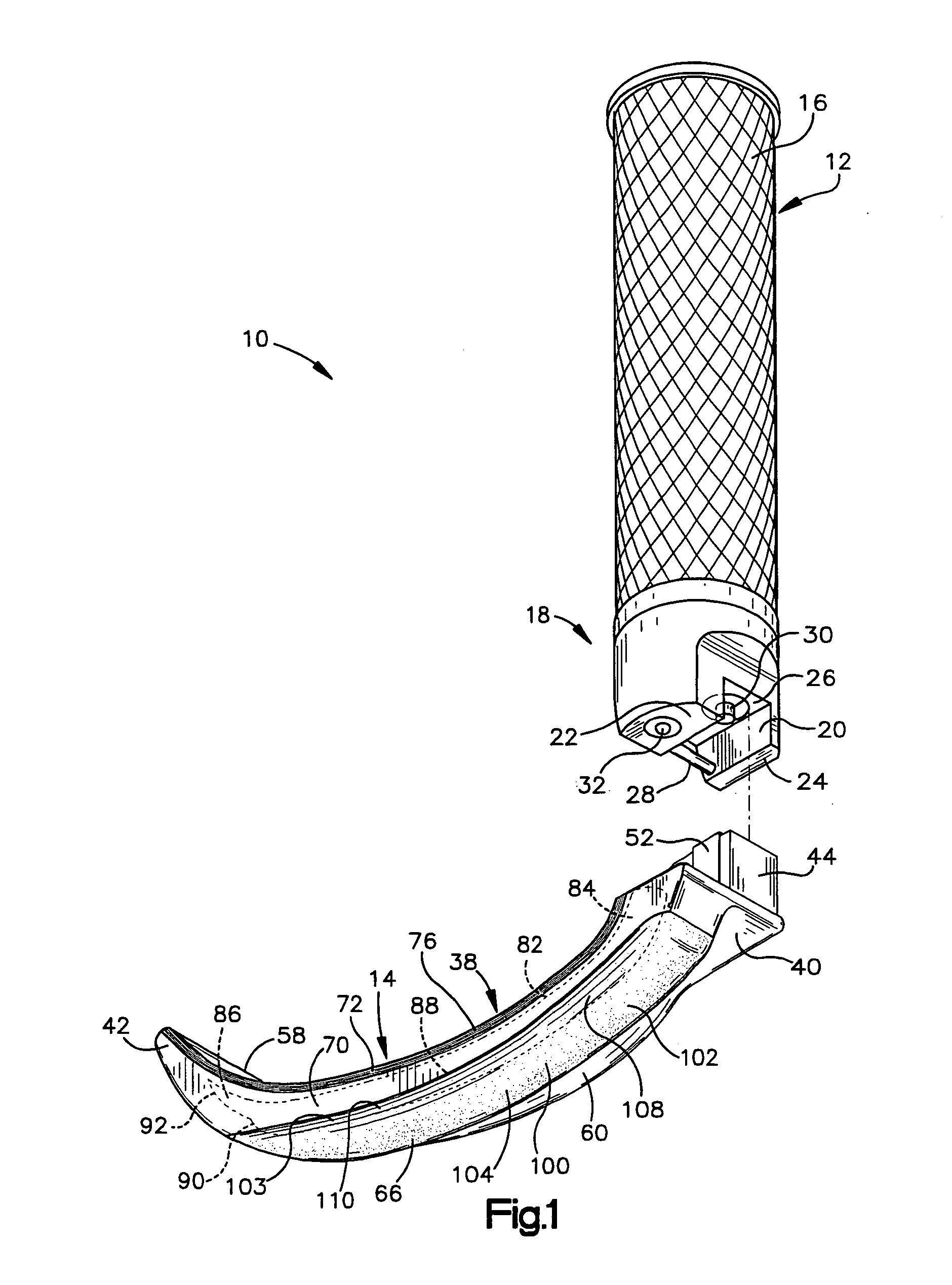
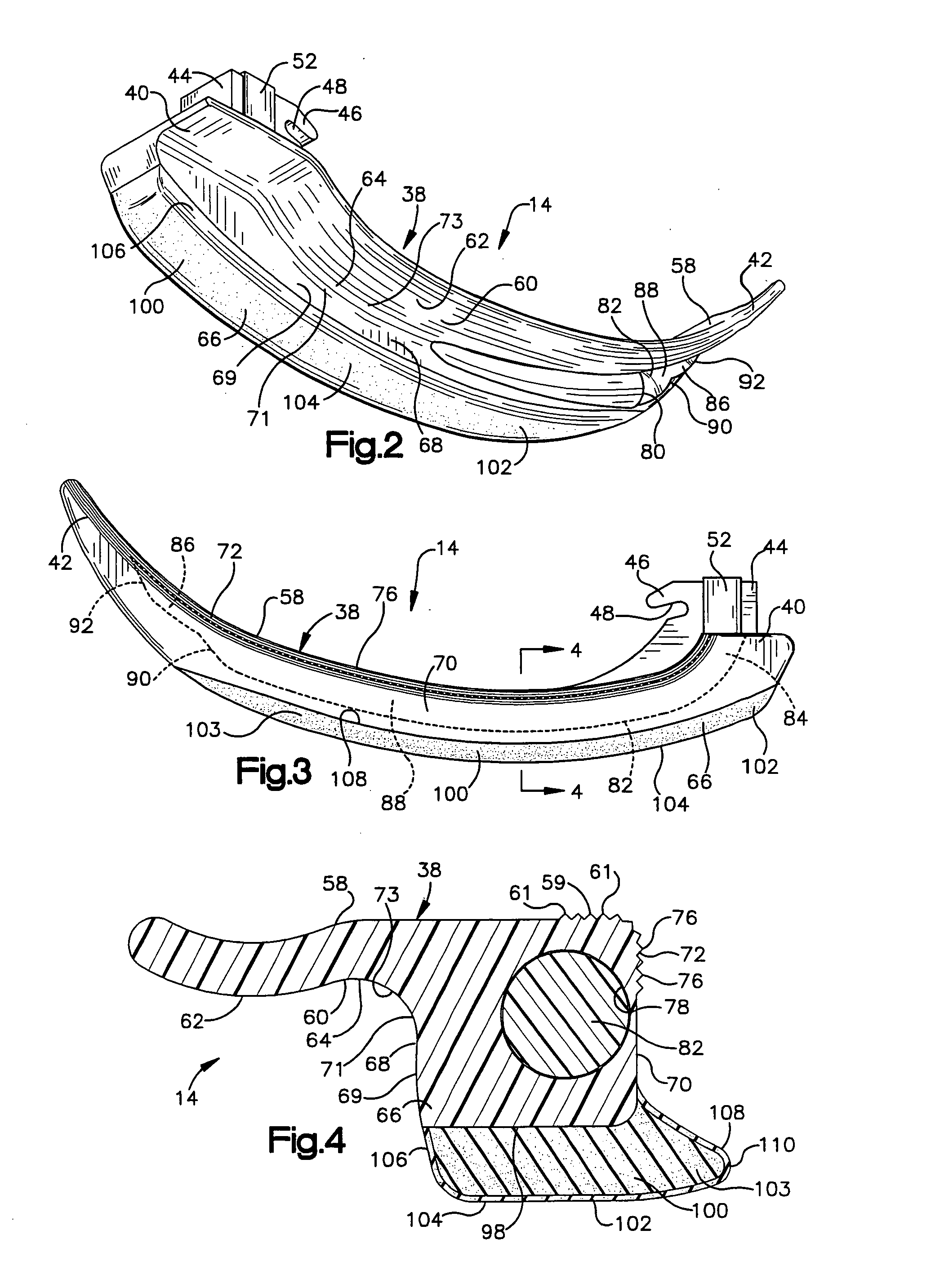
[0038] the laryngoscope blade 114 includes a generally straight main body portion or skeleton 138 having a first end 140 and a second opposite end 142. The first end 140 is detachably connectable to the handle 12 shown in FIG. 1. The second end 142 (FIG. 5) is insertable into a patient's mouth. The main body portion 138 may be made of any suitable rigid material, such as a rigid plastic material. It is contemplated that the blade 114 may be disposable after use.
[0039] The blade 114 is connected to the handle 12 by inserting the rod 28 into a recess 48 defined by a hook 46 on the blade 114. The blade 114 is then pivoted about the rod 28 to pivot a rectangular projection 44 into the recess 20 in the handle 12. A shim portion 52 of the blade 114 engages the walls 22 and 24 of the handle 12 to create an interference fit between the blade and the handle. The shim portion 52 also engages the switch 30 to activate the light source 32. Accordingly, the blade 114 is securely connected to th...
third embodiment
[0048] the laryngoscope blade 214 (FIG. 6) includes an arcuate main body portion or skeleton 238 having a first end 240 and a second opposite end 242. The first end 240 is detachably connectable to the handle 12 shown in FIG. 1. The second end 242 (FIG. 6) is insertable into a patient's mouth. The main body portion 238 may be made of any suitable rigid material, such as a rigid plastic material. It is contemplated that the blade 214 may be disposable after use.
[0049] The blade 214 is connected to the handle 12 by inserting the rod 28 into a recess 48 defined by a hook 46 on the blade 214. The blade214 is then pivoted about the rod 28 to pivot a rectangular projection 44 into the recess 20 in the handle 12. A shim portion 52 of the blade 214 engages the walls 22 and 24 of the handle 12 to create an interference fit between the blade 214 and the handle. The shim portion 52 also engages the switch 30 to activate the light source 32. Accordingly, the blade 214 is securely connected to ...
PUM
 Abstract
Description
Claims
Application Information