Retractile Finger For Fitting To Grain Harvester Auger Main Shaft

Active Publication Date: 2011-03-17
AGCO DO BRASIL COMERCIO E IND
View PDF40 Cites 6 Cited by
  • Summary
  • Abstract
  • Description
  • Claims
  • Application Information

AI Technical Summary

Benefits of technology

[0010]A fifth objective of this invention consists of providing a retractile finger

Problems solved by technology

This groove or fusible part requires a retaining system for the retractile finger so that, when the finger breaks, the above-mentioned system retains the broken part of the finger in th

Method used


Image

  • Retractile Finger For Fitting To Grain Harvester Auger Main Shaft
  • Retractile Finger For Fitting To Grain Harvester Auger Main Shaft
  • Retractile Finger For Fitting To Grain Harvester Auger Main Shaft

Examples


Example

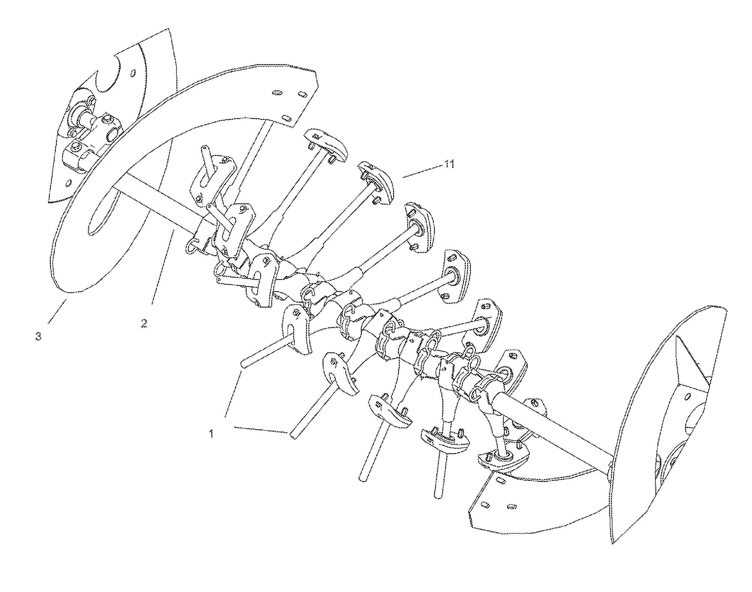
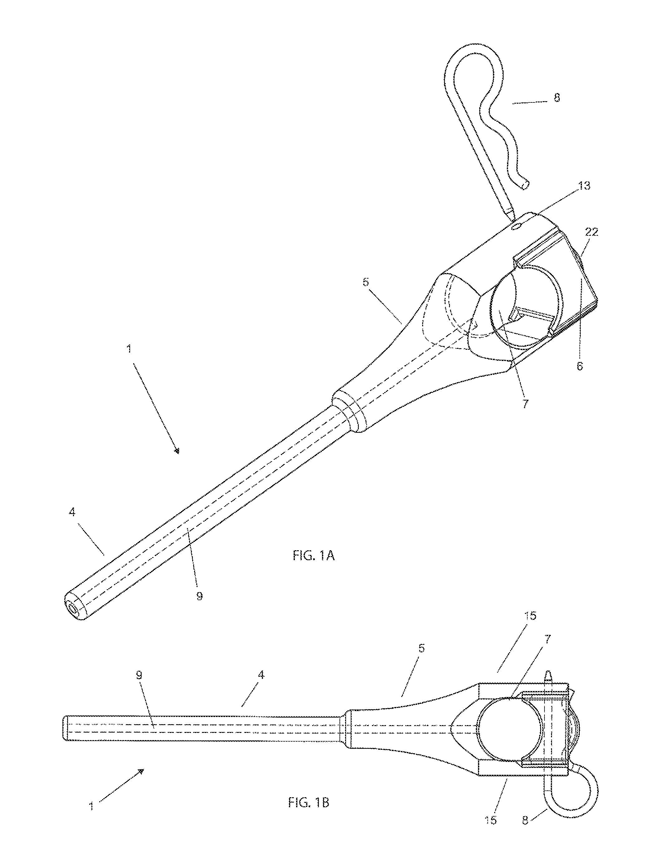
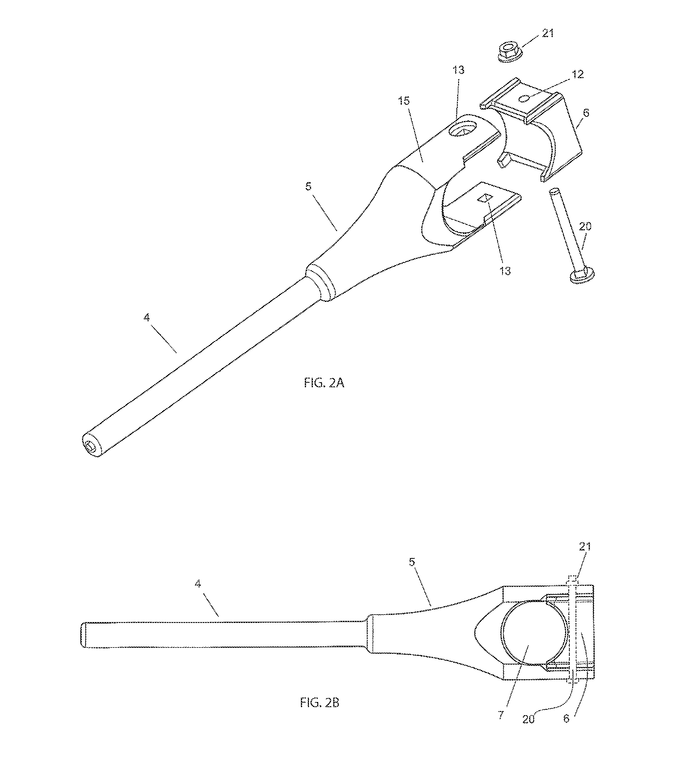
[0020]As can be seen from FIGS. 1A, 1B, 2A and 2B, the retractile finger 1 comprises an elongated portion 4 having at one of its ends a portion in the form of a guide 5 which ends in a U-shaped region. The elongated portion 4 and the portion in the form of a guide 5 form a complete part and are made from ultra-high molecular weight (UHMW) polyethylene.

[0021]The retractile finger 1 also comprises a closing part 6 (see FIG. 2A), also U-shaped, fitted next to the portion in the form of a guide 5. The closing part 6 is preferentially made of UHMW, possibly also being made of any other plastics material or even metal material.

[0022]The U shapes of the portion in the form of a guide 5 and of the closing part 6, when combined, form a cast hole 7 which runs transversely to the retractile finger 1.

[0023]The cast hole 7 is suitably formed to clasp the main shaft 2 of the snail 3 of a grain harvester (not shown). For illustrative purposes, FIG. 3 schematically shows a plurality of retractile f...


PUM


Abstract

The invention relates to a retractile finger (1) for fitting to a grain harvester auger (3) main shaft (2), which retractile finger comprises an elongated portion (4) having at one of its ends a portion in the form of a guide (5) for fitting to the above-mentioned shaft (2), the elongated portion (4) and the portion in the form of a guide (5) being formed in one piece made of polyethylene with a molar mass of between 3.9 and 10.5 million g/mol.

Description

[0001]This invention relates to a retractile finger for use in a rotatable auger assembly of a grain harvesting machine, more particularly for fitting to the main shaft of the machine's auger.DESCRIPTION OF THE PRIOR ART[0002]The front portion of grain harvesters usually has a platform provided with a rotatable auger with a main shaft, to which are fitted several retractile fingers which pull the straw and grain cut into the machine.[0003]At present, various different types of retractile fingers are used in grain harvester auger installations. One example is retractile fingers made of solid steel with heat treatment and a cast steel bush to act as a guide in fitting to the auger main shaft. In this case, the finger is formed by an elongated part made of steel which is fitted to the bush by a screw thread system.[0004]A second example is retractile fingers made of solid steel with heat treatment, with a fusible part or groove made in their elongated body, the finger also comprising a...

Claims


Application Information

Patent Timeline
IPC IPC(8): A01D89/00
CPCA01D89/002A01D61/008A01D57/02
Inventor BATU, NERI PRESTES
Owner AGCO DO BRASIL COMERCIO E IND
Why Eureka
Try Eureka