Sliding member and method of manufacturing the same

Inactive Publication Date: 2016-06-30
TOYOTA JIDOSHA KK +1
View PDF4 Cites 6 Cited by
  • Summary
  • Abstract
  • Description
  • Claims
  • Application Information

AI Technical Summary

Benefits of technology

[0012]According to the invention, an epoxy resin-based sliding member having an equivalent or lower friction coefficient compared to a DLC-based sliding member can be obtained. According to the invention, an epoxy resin-based sliding member having an equivalent or lower friction coefficient compared to a DLC-based sliding member can be easily obtained. In this specification, “ha

Problems solved by technology

Therefore, productivity is low, high costs are inevitable, and thus it is difficult

Method used


Image

  • Sliding member and method of manufacturing the same
  • Sliding member and method of manufacturing the same
  • Sliding member and method of manufacturing the same

Examples


Example

Reference Examples 1 and 2

[0082]100 parts by mass of JER828 (liquid, bifunctional bisphenol A type epoxy resin, manufactured by Mitsubishi Chemical Corporation) as an epoxy resin; 1 part by mass (Reference Example 1) or 5 parts by mass (Reference Example 2) of BYK-Silclean 3720 (solid content: 25 mass %; manufactured by BYK-Chemie Japan K.K.) as a silicon leveling agent; and 3 parts by mass of CPI-210S (photoacid generator; 100 parts by mass of non-volatile components; manufactured by San-Apro Ltd.) as a polymerization initiator were mixed with each other to prepare a mixed solution. This mixed solution was set as a hard coating solution (curing composition).

Comparative Reference Examples 1 and 2

[0083]100 parts by mass of a bifunctional acrylate resin IRR-214-K (manufactured by Daicel-Allnex Ltd.) instead of the epoxy resin; 5 parts by mass (Comparative Reference Example 1) or 10 parts by mass (Comparative Reference Example 2) of EBI360 (silicon acrylate; manufactured by Daicel-Alln...

Example

Example 1

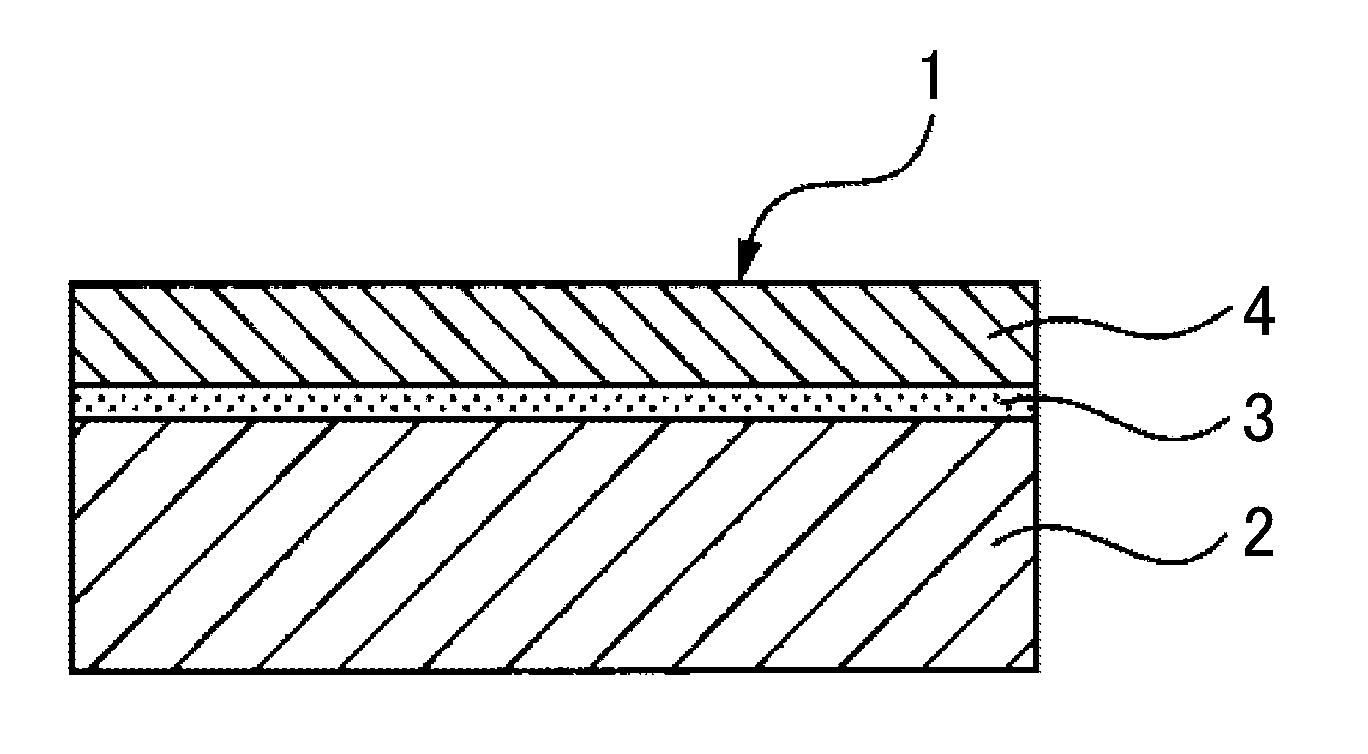
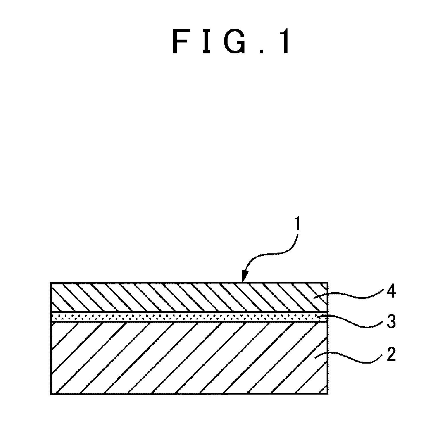
[0084]RAYMAGIC 07 (manufactured by Kanae Paint Co., Ltd.) was cast onto a single surface of an aluminum plate (mirror surface) using a wire bar (No. 3). Next, the aluminum plate was left to stand in an oven at 100° C. for 1 minute and then was irradiated with UV rays under irradiation conditions: 400 mJ / cm2. As a result, an undercoat primer layer having a thickness of about 2 μm was formed. Next, the hard coating solution of Reference Example 1 was cast onto the primer layer side using a wire bar (No. 30). Next, the aluminum plate was left to stand in an oven at 100° C. for 1 minute, was irradiated with UV rays under irradiation conditions: 400 mJ / cm2, and was heated at 150° C. for 1 hour. As a result, a coating film of the hard coating solution was cured, and an aluminum substrate including an undercoat primer layer having a thickness of about 2 μm and a hard coating layer (resin layer) having a thickness of 40 μm was prepared. Regarding the obtained sample, the measuremen...

Example

Example 2

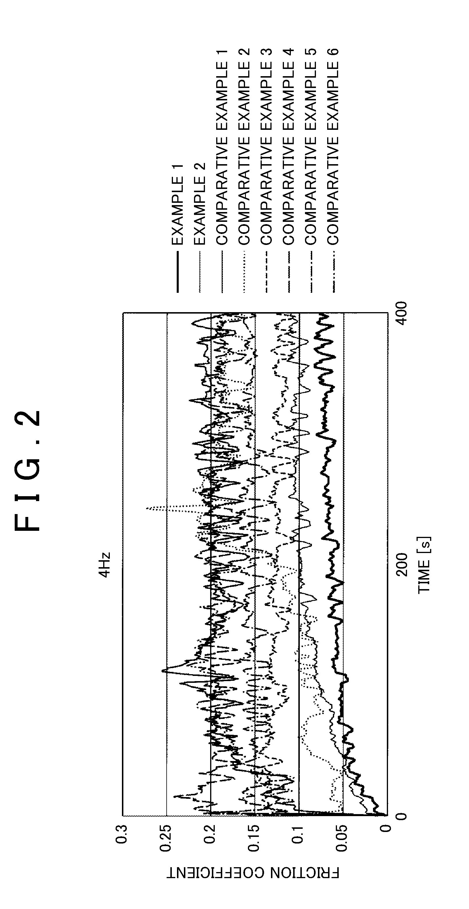
[0085]An aluminum plate including an undercoat primer layer having a thickness of about 2 μm and a hard coating layer having a thickness of 40 μm was prepared using the same method as in Example 1, except that the hard coating solution of Reference Example 2 was cast instead of the hard coating solution of Reference Example 1. Regarding the obtained sample, the measurement of the surface roughness and the friction test were performed. The friction coefficients were 0.1 (rank B) at 4 Hz, 0.09 (rank A) at 16 Hz, and 0.08 (rank A) at 20 Hz. FIGS. 2 to 4 show the results of measuring a friction coefficient together with other results. The table of FIG. 5 shows the results of evaluating peeling resistance after the friction test together with other results. The table of FIG. 13 shows the results of measuring the surface roughness of the sample before the friction test together with other results. FIG. 15 shows a copy of a surface image of the sample after the friction test.


PUM

PropertyMeasurementUnit
Fractionaaaaaaaaaa
Thicknessaaaaaaaaaa
Thicknessaaaaaaaaaa

Abstract

A sliding member includes: a metal substrate; an undercoat primer layer that is formed on a sliding surface of the metal substrate; and a resin layer that is formed on the undercoat primer layer. The resin layer is formed by curing a composition layer containing a bifunctional bisphenol A type epoxy resin, a leveling agent, and a polymerization initiator.

Description

INCORPORATION BY REFERENCE[0001]The disclosure of Japanese Patent Application No. 2014-263676 filed on Dec. 25, 2014 including the specification, drawings and abstract is incorporated herein by reference in its entirety.BACKGROUND OF THE INVENTION[0002]1. Field of the Invention[0003]The present invention relates to a sliding member and a method of manufacturing the same and, specifically, relates to an epoxy resin-based sliding member having an equivalent or higher effect of reducing a friction coefficient compared to a diamond-like carbon (DLC)-based sliding member and a method of manufacturing the same.[0004]2. Description of Related Art[0005]In an internal combustion engine such as an engine or the like of an automobile, sliding members are used for various units including a piston skirt portion. Regarding these sliding members, various techniques have been developed in order to comply with, for example, CAFE standards for global environmental protection which state that energy l...

Claims


Application Information

Patent Timeline
IPC IPC(8): F01L1/16F16H7/08F01L1/06F02F3/10F01L1/18
CPCF01L1/16F02F3/10F16H2007/0872F01L1/06F16H7/0829F01L1/18B05D5/08F02F3/0084F16C33/201F16C33/208C09D163/00F16C2240/60F16C33/206F16C2208/86
Inventor FUKUTOMI, IPPEIIKEDA, NAOYAMANABE, KAZUYOSHIKIKUCHI, SHINJI
Owner TOYOTA JIDOSHA KK
Why Eureka
Try Eureka