Ball valve and sealing element for ball valve

Inactive Publication Date: 2018-11-29
SCHAEFFLER TECH AG & CO KG
View PDF12 Cites 6 Cited by
  • Summary
  • Abstract
  • Description
  • Claims
  • Application Information

AI Technical Summary

Benefits of technology

[0027]the first sealing ring is a stamped annular PTFE sheet. First, PTFE has a very low friction coefficient. Furthermore, PTFE is softer than PVDF. The first sealing ring can form a contact seal with the ball under a smaller acting force, so that the friction torque between the first sealing ring and the spherical surface of the ball is relatively small, and the first sealing ring does not

Problems solved by technology

The issue to be addressed by the invention is that the existing sealin

Method used


Image

  • Ball valve and sealing element for ball valve
  • Ball valve and sealing element for ball valve
  • Ball valve and sealing element for ball valve

Examples


Example

First Embodiment

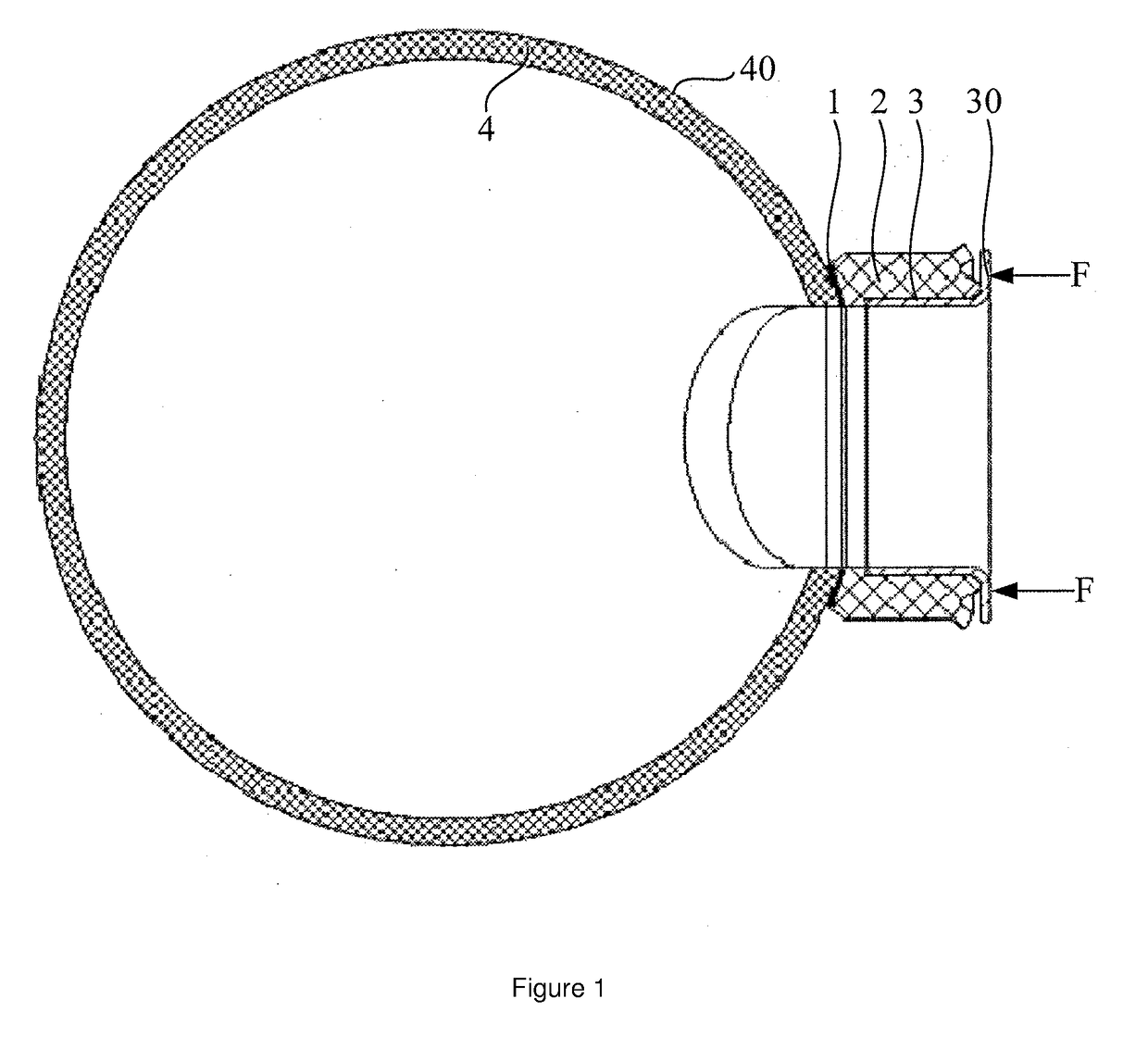
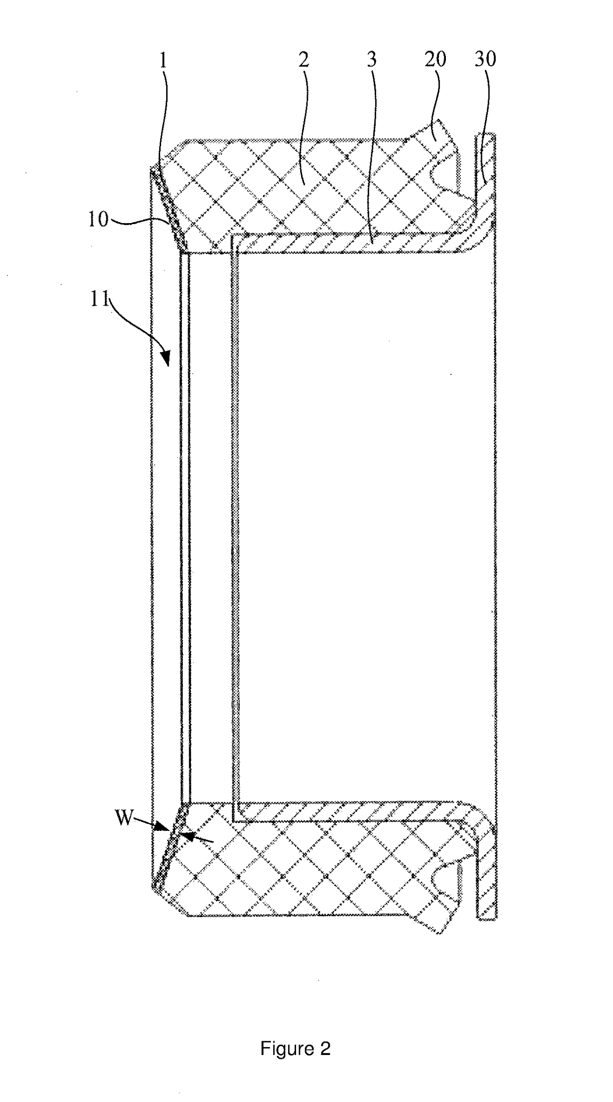
[0037]With reference to FIG. 1 to FIG. 2, this embodiment provides a sealing element for a ball valve. The sealing element comprises a first sealing ring 1 and a second sealing ring 2. The central axes (not shown) of the first sealing ring 1 and the second sealing ring 2 are parallel, and the first sealing ring and the second sealing ring are made of different materials. The first sealing ring 1 is located on a side of the second sealing ring 2 facing towards a ball 4 in the ball valve in an axial direction, and is used to make contact with a spherical surface 40 of the ball 4 to form a seal, so as to prevent a medium from leaking from the spherical surface 40 of the ball 4. In the technical solution of the invention, what is called the axial direction refers to the axial direction of the sealing element.

[0038]The first sealing ring 1 is a stamped annular PTFE (Polytetrafluoroethylene) sheet. That is, a stamping die is used to perform stamping processing on an annula...

Example

Second Embodiment

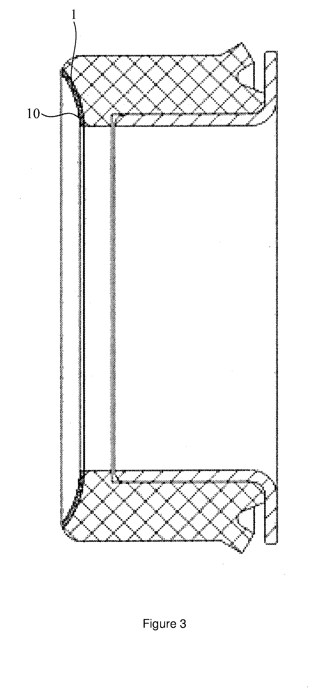
[0052]The differences between the second embodiment and the first embodiment are as follows: As shown in FIG. 3, in the second embodiment, the sealing surface 10 of the first sealing ring 1 is a spherical surface whose curvature is equal to the curvature of the spherical surface of the ball (not shown). That is, the shape of the sealing surface 10 matches the shape of the spherical surface of the ball. When the sealing surface 10 is in pre-contact with the spherical surface, the entire sealing surface 10 makes contact with the spherical surface. The benefit of configuring the sealing surface 10 as a spherical surface is that after the sealing element is assembled on the ball valve, a relatively small pressing force in the axial direction may be applied to the sealing element. In this way, it can still be ensured that the sealing surface 10 stays in tight contact with the spherical surface. Because the pressing force is relatively small, the friction torque between t...

Example

Third Embodiment

[0053]The differences between the third embodiment and the first embodiment are as follows: as shown in FIG. 4, in the third embodiment, an annular concave cavity 14 surrounding a central axis O is arranged on one side of the first sealing ring 1 facing towards the ball 4 in an axial direction (only a part is schematically shown with a dotted line in the figure). The direction pointing from an axial end of the flaring opening enclosed by the sealing surface 10 to the other axial end is defined as an extending direction A. After the sealing element is assembled on the ball valve, partial portions of the first sealing ring 1 located on two sides of the annular concave cavity 14 in the extending direction A both make contact with the spherical surface 40, such that the annular concave cavity 14 and the spherical surface 40 enclose an annular sealing cavity. When leaking from one of the partial portions, the medium flows into the annular concave cavity 14, and as a resul...


PUM


Abstract

A sealing element for a ball valve with a first sealing ring and a second sealing ring whose central axes are parallel, the first sealing ring and the second sealing ring being made of different materials, and the first sealing ring being located on a side of the second sealing ring facing towards a ball in a ball valve in an axial direction, and being used to make contact with a spherical surface of the ball to form a seat The first and second sealing rings are fixed together, and the first sealing ring is a stamped annular polytetrafluoroethylene (PTFE) sheet. Since PTFE has a very low friction coefficient, the friction torque between the first sealing ring and the spherical surface of the ball is relatively small, and the first sealing ring does not wear easily and is not prone to sealing failure. A ball valve using the sealing element is also disclosed.

Description

[0001]The present application claims priority of Chinese Patent Application No. 201510802493.5, filed on 19 Nov. 2015 and entitled “Ball valve and sealing element for ball valve”, which is incorporated herein by reference in its entirety.[0002]The present application claims priority of Chinese Patent Application No. 201610405299.8, filed on 8 Jun. 2016 and entitled “Ball valve and sealing element for ball valve”, which is incorporated herein by reference in its entirety.TECHNICAL FIELD[0003]The present invention relates to the technical field of ball valves, and in particular to a ball valve and a sealing element for a ball valve.BACKGROUND[0004]A ball valve can enable or disable the flow of a medium, and comprises a ball and a stem. Several channels for the medium to flow through are provided on a spherical surface of the ball. The stem is rotated to drive the ball to rotate to open or close a channel, so as to enable or disable the flow of the medium. A sealing element is arranged...

Claims


Application Information

Patent Timeline
IPC IPC(8): F16K5/20F16K5/06F16K27/06
CPCF16K5/20F16K5/0631F16K27/067F16K5/0678F16K5/0663F16K5/0689F16K5/201F16J15/104F16K5/0673Y10S277/946
Inventor WICHER, SVENNIEBLING, UWELIU, XINZHANG, YUELINARIMA, GILSONLI, MENGZHOU, HUILAN
Owner SCHAEFFLER TECH AG & CO KG
Why Eureka
Try Eureka